Stator winding having transitions

a technology of transitions and windings, applied in the field of electric machines, can solve the problems of increasing the complexity of winding the stator, increasing the cost of winding, and reducing so as to reduce the amount of cross current circulation, reduce the amount of heat generation within the stator, and improve the efficiency of the stator

Inactive Publication Date: 2005-03-03
REMY TECHNOLOGIES LLC
View PDF95 Cites 28 Cited by
  • Summary
  • Abstract
  • Description
  • Claims
  • Application Information

AI Technical Summary

Benefits of technology

[0010] Also, the staggered pattern of the first and second filars of each phase reduces the amount of cross current circulation betwee

Problems solved by technology

These stators, however, are disadvantageous because the windings are typically interlaced, in which the wires are required to alternate outer and inner radial portions of each slot.
These interlaced windings require an interlacing process to interlace the conductors of all the phases prior to inserting the winding into the core or a connection process to connect the individual U-shaped conductors and therefore disadvantageously increase the complexity of placing the winding the stator.
However, bi-filar windings are subject to overheating due to cross

Method used


Image

  • Stator winding having transitions
  • Stator winding having transitions
  • Stator winding having transitions

Examples


Embodiment Construction

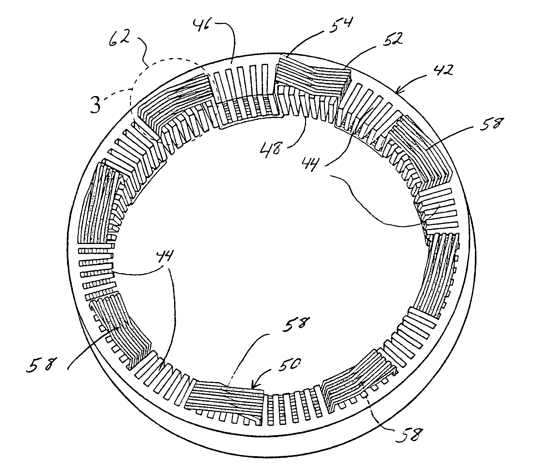
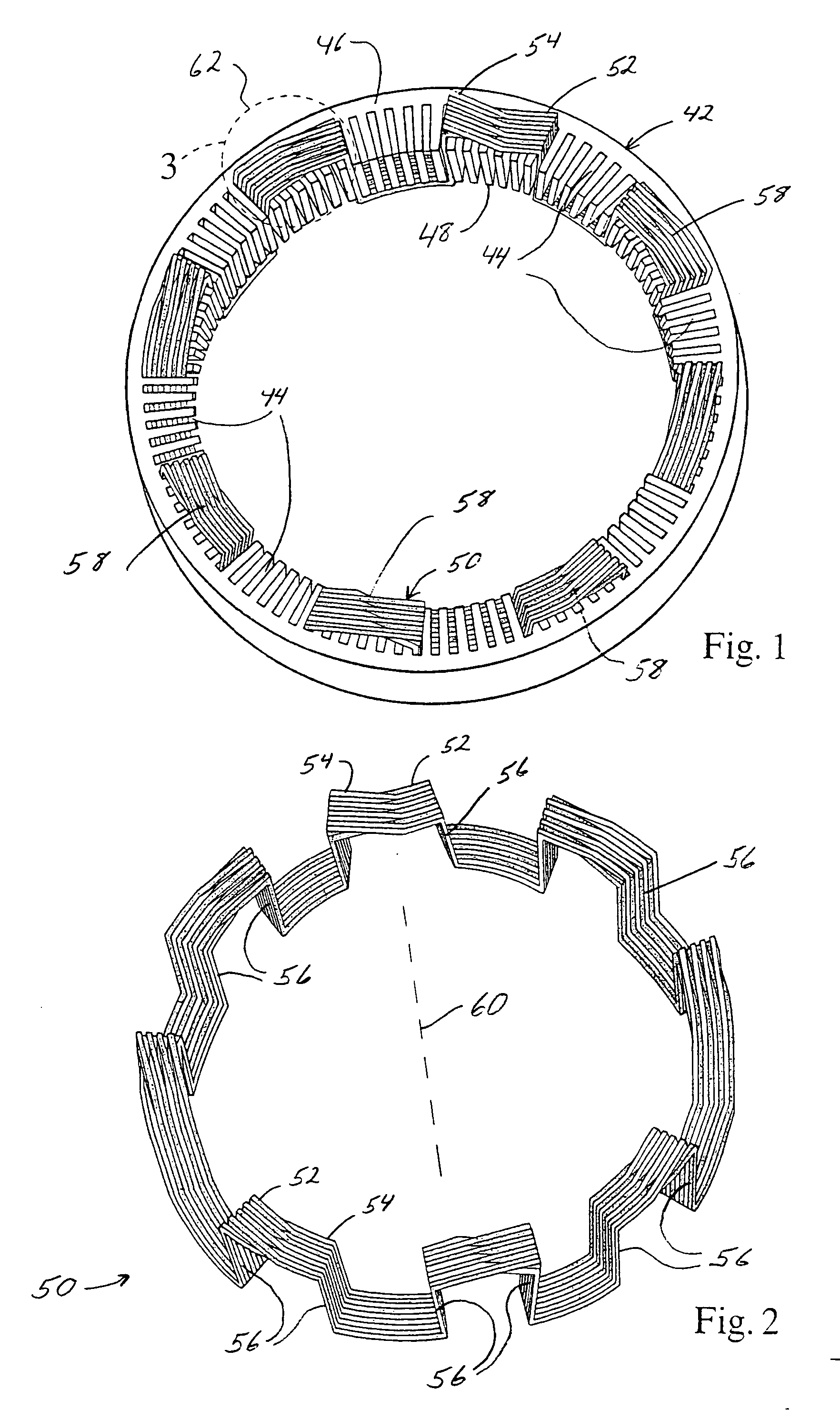
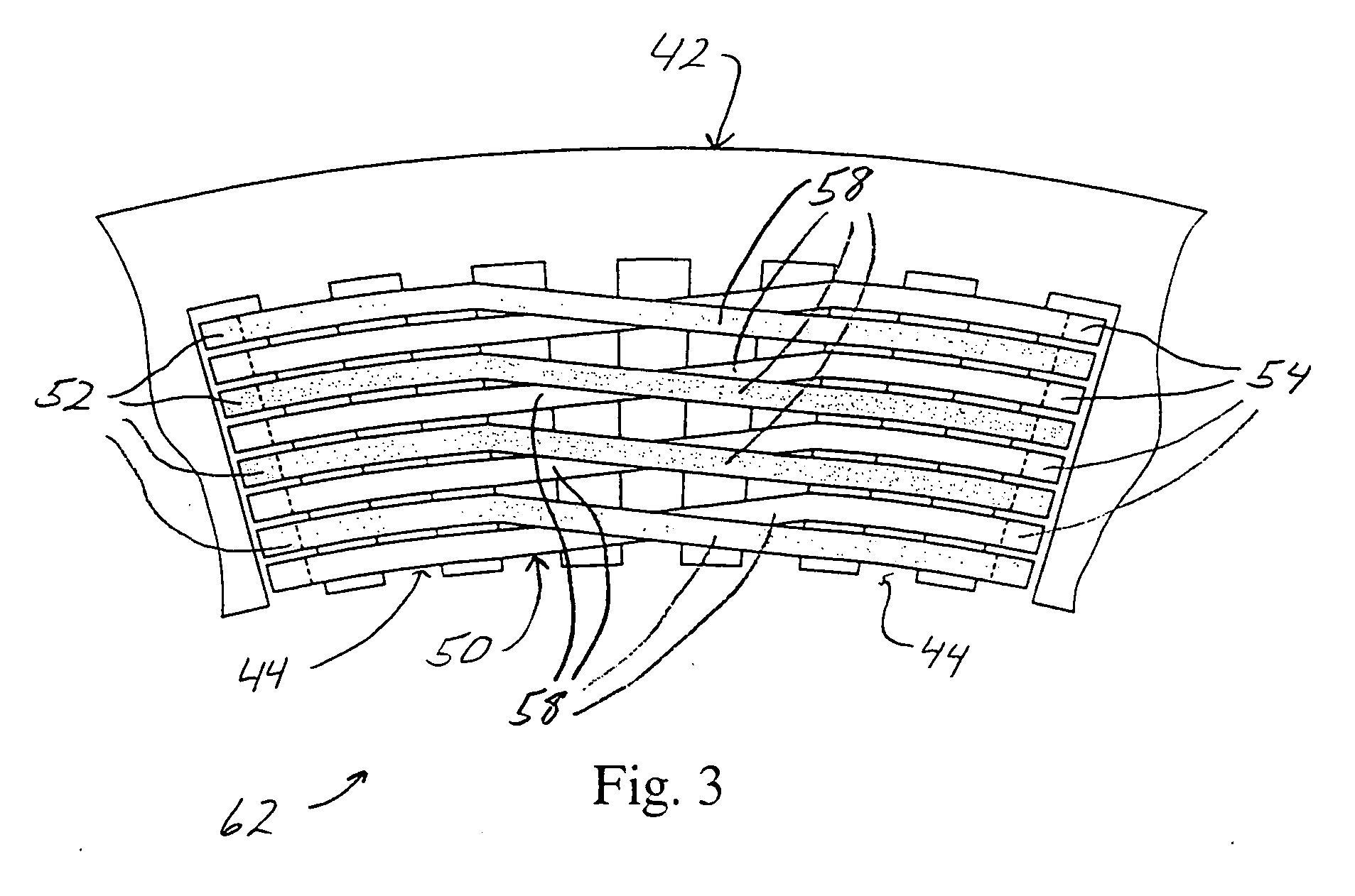
[0023] Referring now to FIGS. 1-3, a stator of the present invention is shown generally at 40. For simplicity, FIGS. 1-5 depict only one phase of a six phase winding and do not show necessary shape of the end loop segments that allow nesting of the end loop segments of all the phases, such as the cascade winding shown in FIGS. 9, 10, 11a and 11b. Although the filars of one phase are shown in FIGS. 1-5 as having the same phase angle, they may also be shifted with respect to each other such that they are out of phase by 180 electrical degrees as can be seen in FIGS. 11a and 11b. The stator 40 includes a generally cylindrically-shaped stator core 42 having a plurality of circumferentially spaced and axially-extending core slots 44. The core slots 14 define a plurality of teeth 15 there between, which are connected to one another by a yoke 19. The core slots 44 extend between a first end 46 of the stator core 42 and a second end 48 of the stator core 42. The stator core 42 includes a st...


PUM


Abstract

A stator for an electric machine includes a generally cylindrically-shaped stator core having a plurality of circumferentially spaced core slots. A stator winding includes a plurality of phases, each including at least a first filar and a second filar extending circumferentially around the stator core to form a plurality of layers. Each of the filars is a conductor having a plurality of slot segments disposed in the core slots. The slot segments are alternately connected at the first and second ends of the stator core by a plurality of end loop segments that may form a cascaded winding pattern. The plurality of filars of each phase alternating radial positions with one another within at least one end loop segment at discreet locations around the stator core such that the average radial position of the slot segments of the first filar conductors is substantially equal to that of the second filar.

Description

CROSS-REFERENCE TO RELATED APPLICATIONS [0001] This application is a continuation-in-part of U.S. patent application Ser. No. 10 / 850,012, filed May 19, 2004 entitled “Stator Assembly With Cascaded Winding and Method of Making Same”, which is, in turn, a continuation-in-part of U.S. patent application Ser. No. 10 / 443,441, filed May 22, 2003, which claims priority from Provisional Application No. 60 / 454,996, filed Mar. 14, 2003, the respective disclosures of each of which are hereby incorporated by reference. This application is also a continuation-in-part of U.S. patent application Ser. No. 10 / 265,529 filed Oct. 7, 2002, which, in turn, is a continuation-in-part of U.S. patent application Ser. No. 10 / 056,890 filed Jan. 24, 2002, the respective disclosures of each of which are hereby incorporated by reference.BACKGROUND OF THE INVENTION [0002] The present invention relates generally to electric machines and, in particular, to a stator winding for an electric machine having cascaded en...

Claims


Application Information

Patent Timeline
IPC IPC(8): H02K3/12H02K3/28H02K3/50H02K15/00
CPCH02K3/12H02K3/50H02K15/0037H02K3/28
Inventor CHEN, HANYANG BENNEET, KIRK E.
Owner REMY TECHNOLOGIES LLC
Why Eureka
Try Eureka