Semiconductor device
a technology of semiconductor devices and semiconductors, applied in semiconductor devices, semiconductor/solid-state device details, electrical apparatus, etc., can solve the problems of reducing the communication distance between transmitting and receiving signals, and achieve the effect of reducing eddy current, reducing eddy current, and inhibiting a decrease in magnetic field strength
- Summary
- Abstract
- Description
- Claims
- Application Information
AI Technical Summary
Benefits of technology
Problems solved by technology
Method used
Image
Examples
first embodiment
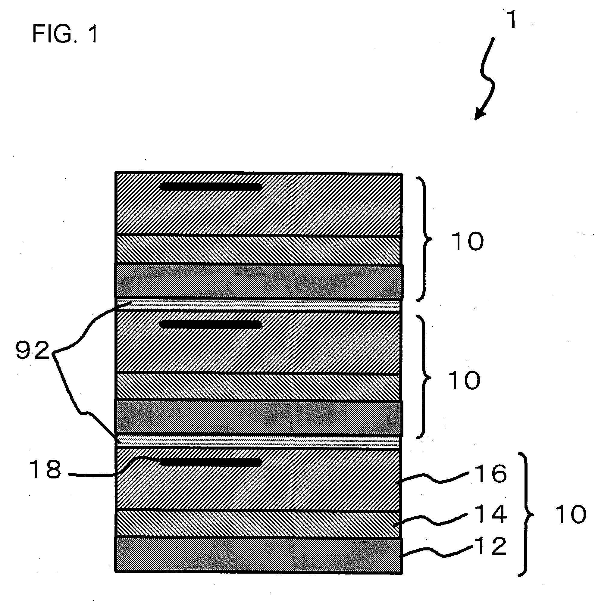
[0016]FIG. 1 is a cross-sectional view, showing first embodiment of a semiconductor device according to the present invention. A semiconductor device 1 includes a semiconductor chip 10. In the present embodiment, three semiconductor chips 10 are stacked. The semiconductor chips 10 are adhered with adhesive agents 92.
[0017]Each of the semiconductor chips 10 includes a semiconductor substrate 12, a semiconductor layer 14 and an interconnect layer 16. The semiconductor substrate 12 is, for example, a silicon substrate. The semiconductor substrate 12 has a specific resistance ρ1 (first specific resistance). A typical value of ρ1 is, for example, 1,000 Ωcm. Preferably, the specific resistance may be presented as: ρ1≧200 Ωcm, and more preferably, ρ1≧500 Ωcm.
[0018]A semiconductor layer 14 is provided on the semiconductor substrate 12. The semiconductor layer 14 is, for example, a silicon layer formed by an epitaxial growing process. Such semiconductor layer 14 exhibits a specific resistanc...
second embodiment
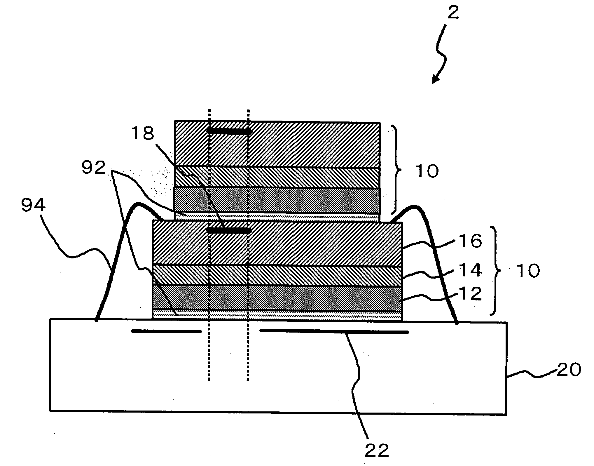
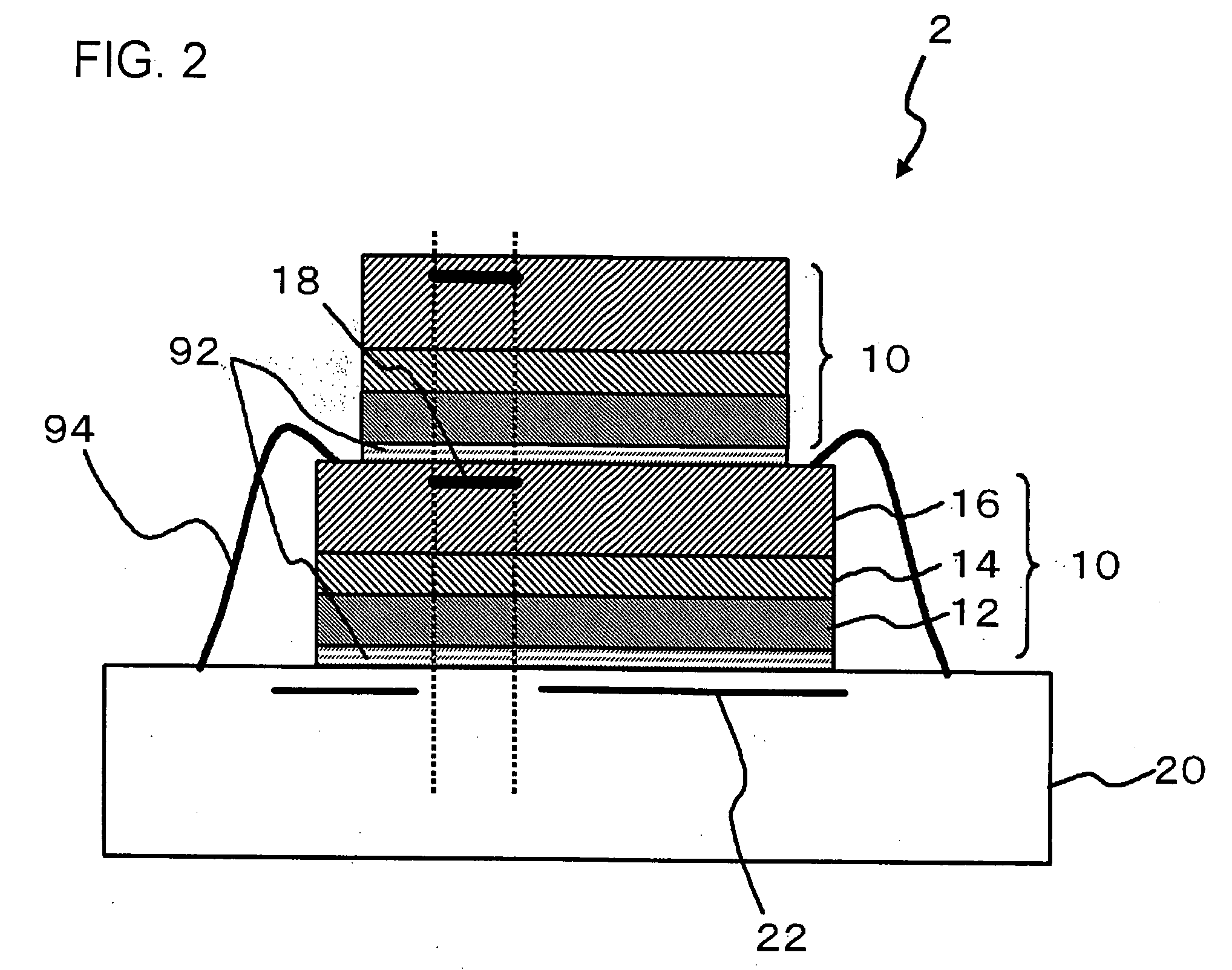
[0029]FIG. 2 is a cross-sectional view, showing second embodiment of a semiconductor device according to the present invention. A semiconductor device 2 comprises a semiconductor chip 10 and a printed circuit board 20. A configuration of the semiconductor chip 10 is equivalent to that described in reference to FIG. 1. In the present embodiment, two semiconductor chips 10 are stacked, and the semiconductor chip 10 in the bottom layer is attached to the printed circuit board 20 by a wire bonding. More specifically, the semiconductor chip 10 of the bottom layer is electrically coupled with the printed circuit board 20 by a wire 94. A coupling between the semiconductor chips 10 and a coupling of the semiconductor chip 10 with the printed circuit board 20 are achieved by the adhesive agent 92.
[0030]The interconnect 22 of the printed circuit board 20 is provided in a region that has no portion overlapping with the inductor 18 of the semiconductor chip 10 in plan view. More specifically, t...
third embodiment
[0032]FIG. 3 is a cross-sectional view, showing third embodiment of a semiconductor device according to the present invention. A semiconductor device 3 comprises a semiconductor chip 10 and a printed circuit board 20. A configuration of the semiconductor chip 10 is equivalent to that described in reference to FIG. 1. Further, a configuration of the printed circuit board 20 is equivalent to that described in reference to FIG. 2. In the present embodiment, two semiconductor chips 10 are stacked, and the semiconductor chip 10 in the bottom layer is attached to the printed circuit board 20 by a flip chip bonding. More specifically, the semiconductor chip 10 of the bottom layer is coupled to the printed circuit board 20 by a bump 30, in a situation that the interconnect layer 16 thereof is oriented toward the printed circuit board 20. Specifically, an electroconductive pad 42 (first pad) and an electroconductive pad 44 (second pad) are formed in each of the semiconductor chip 10 and the ...
PUM
 Abstract
Description
Claims
Application Information
 - R&D
- Intellectual Property
- Life Sciences
- Materials
- Tech Scout
- Unparalleled Data Quality
- Higher Quality Content
- 60% Fewer Hallucinations
Browse by: Latest US Patents, China's latest patents, Technical Efficacy Thesaurus, Application Domain, Technology Topic, Popular Technical Reports.
© 2025 PatSnap. All rights reserved.Legal|Privacy policy|Modern Slavery Act Transparency Statement|Sitemap|About US| Contact US: help@patsnap.com


