Antenna apparatus

a technology of antenna apparatus and antenna elements, which is applied in the direction of antennas, antenna details, antenna feed intermediates, etc., can solve the problems of increasing the size of the antenna apparatus, reducing the radiation efficiency of the antenna element, and reducing the effective use of radio waves. , to achieve the effect of improving the antenna radiation efficiency and reducing the siz

Active Publication Date: 2007-11-29
TOSHIBA CLIENT SOLUTIONS CO LTD
View PDF3 Cites 41 Cited by
  • Summary
  • Abstract
  • Description
  • Claims
  • Application Information

AI Technical Summary

Benefits of technology

[0010]In view of the above-described problems, it is an object of the present invention to provide an antenna apparatus which can realize both an improvement in antenna radiation efficiency and a reduction in size.

Problems solved by technology

For example, in an antenna apparatus used in a mobile communication terminal, radio frequency waves radiated from an antenna element produce a transmission loss in a propagation process.
Therefore, excessive intensive radio frequency waves more than necessary must be transmitted, and hence there is problem in effective use of the radio waves.
However, when a distance between the antenna element, the electronic component and the printed circuit board is set large, the antenna apparatus is increased in size.
As a result, an antenna apparatus accommodation space in a case of a mobile communication terminal becomes large, whereby an increase in size of the terminal is unavoidable.
Furthermore, even if a magnetic material plate is arranged on the side opposite to the side where an antenna of the printed circuit board is set, antenna radiation characteristics are not improved.

Method used


Image

  • Antenna apparatus
  • Antenna apparatus
  • Antenna apparatus

Examples


eighth embodiment

[0112]In an eighth embodiment according to the present invention, when interposing and arranging magnetic members between a ground plane of a printed circuit board and elements of a dipole antenna, strip-like magnetic members each having a narrow width are respectively arrange to face parts of respective intermediate portions of the pair of elements constituting the dipole antenna close to ends thereof.

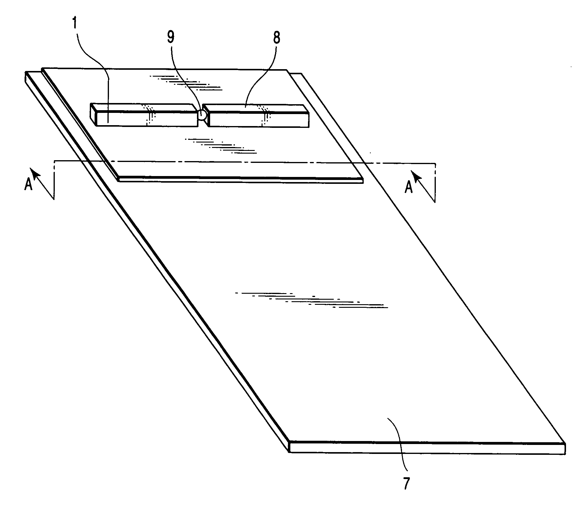
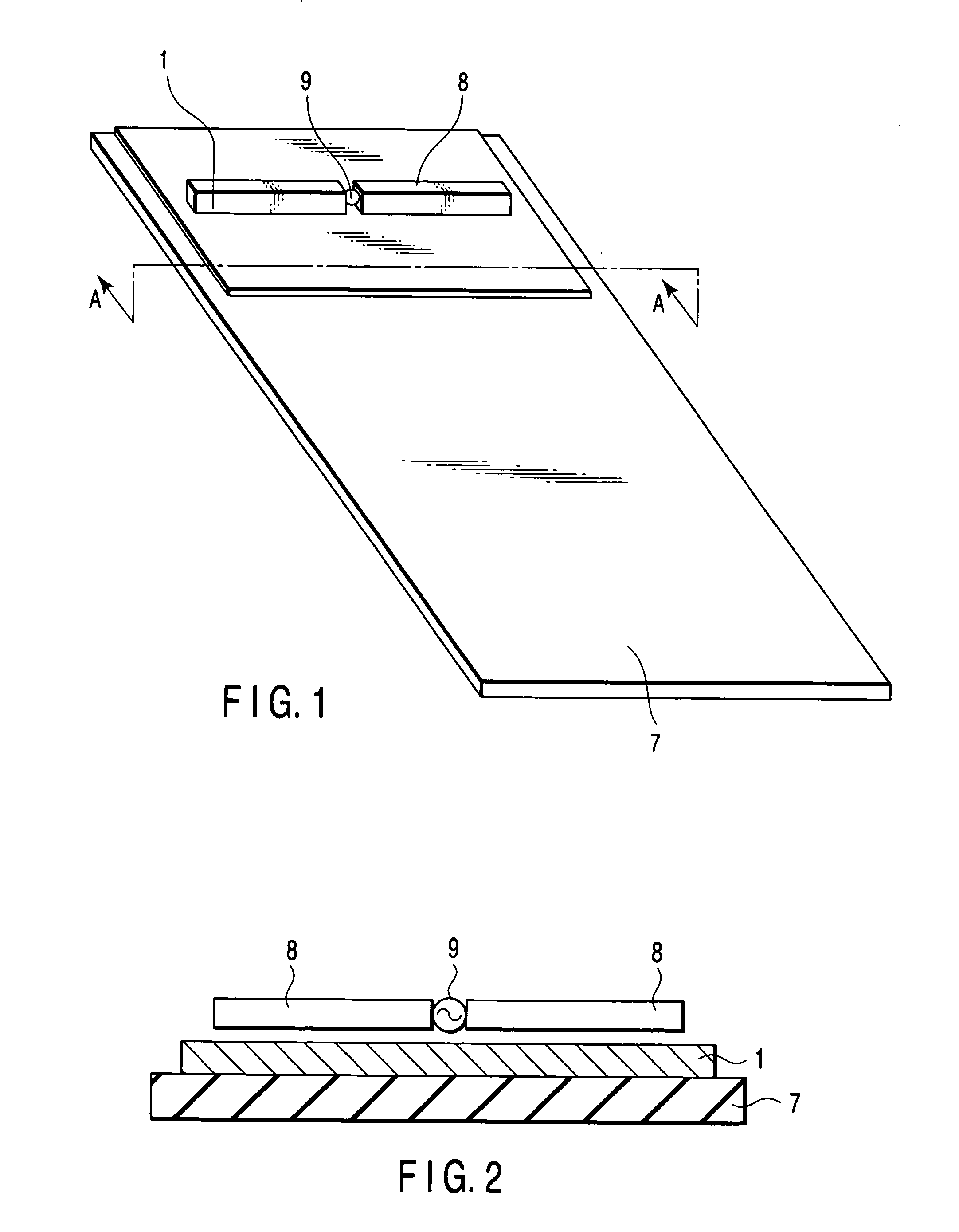
[0113]FIG. 21 is a plan view showing this structure. As shown in this drawing, strip-like magnetic members 1e and 1e each having a narrow width are respectively arranged on a ground plane of a printed circuit board 7 to face parts of intermediate portions of a pair of elements 8 and 8 constituting a dipole antenna close to ends thereof. It is to be noted that a structure of each antenna element 8 and 8, the printed circuit board 7 and the magnetic members 1e and 1e is the same as that described in the first embodiment.

[0114]Even if such magnetic members 1e and 1e are provided, input i...

ninth embodiment

[0115]In a ninth embodiment according to the present invention, when interposing and arranging magnetic members between a ground plane of a printed circuit board and element of a dipole antenna, strip-like magnetic members each having a narrow width are respectively arranged to face parts of intermediate portions of the pair of elements constituting the dipole antenna close to a feed point.

[0116]FIG. 23 is a plan view showing this structure. As shown in the drawing, strip-like magnetic members 1f and 1f each having a narrow width are respectively arranged on a ground plane of a printed circuit board 7 to face parts of intermediate portions of a pair of elements 8 and 8 constituting a dipole antenna close to a feed point 9. It is to be noted that a structure of each antenna element 8 and 8, the printed circuit board 7 and the magnetic members 1f and 1f is the same as that described in the first embodiment.

[0117]Even if such magnetic members 1f and 1f are provided, a higher input impe...

12th embodiment

[0126]In a 12th embodiment according to the present invention, a magnetic member is interposed and arranged between a monopole antenna and a printed circuit board having a metal surface which applies a ground potential to this monopole antenna.

[0127]FIG. 29 is a cross-sectional view showing a schematic configuration of an antenna apparatus according to this 12th embodiment. A magnetic member 1C is interposed and arranged between a printed circuit board having a ground plane and a monopole antenna 8A. The magnetic member 1C has nanogranular structure in which magnetic nanoparticles are three dimensionally dispersed and arranged in an insulating matrix substrate like the magnetic members described in the foregoing embodiments.

[0128]According to the thus configured antenna apparatus, a current distribution on the ground plane of the monopole antenna 1C can be controlled by using the magnetic member 1C.

13th Embodiment

[0129]In a 13th embodiment according to the present invention, when in...


PUM


Abstract

A magnetic member is interposed and arranged between an antenna element and a printed circuit board, and an air member or a dielectric member is interposed between the antenna element and the magnetic member. The magnetic member is constituted of a nanogranular structure in which magnetic nanoparticles with ferromagnetism are three-dimensionally dispersed and arranged in an insulating matrix substrate.

Description

CROSS-REFERENCE TO RELATED APPLICATIONS[0001]This application is based upon and claims the benefit of priority from prior Japanese Patent Application No. 2006-147282, filed May 26, 2006, the entire contents of which are incorporated herein by reference.BACKGROUND OF THE INVENTION[0002]1. Field of the Invention[0003]The present invention relates to an antenna apparatus provided in a wireless communication device which requires a reduction in thickness (low profile), such as a mobile communication.[0004]2. Description of the Related Art[0005]In recent years, with a reduction in size and weight of electronic communication devices, a reduction in size and weight of electronic components has been demanded. A mobile communication terminal performs most of information propagation by transmission / reception of radio frequency waves. A frequency band of a currently utilized radio frequency is over 100 MHz. Thus, attention has been paid to electronic components and printed circuit boards which...

Claims


Application Information

Patent Timeline
Patent Type & Authority Applications(United States)
IPC IPC(8): H01Q1/00
CPCH01Q1/2225H01Q19/30H01Q19/13H01Q1/40
Inventor TSUJIMURA, AKIHIROSATO, KOICHIAMANO, TAKASHIHOTTA, HIROYUKI
Owner TOSHIBA CLIENT SOLUTIONS CO LTD
Why Eureka
Try Eureka