Vertical Heat Treatment System and Automatic Teaching Method for Transfer Mechanism

a technology of transfer mechanism and heat treatment system, which is applied in the direction of instruments, programme control, furniture, etc., can solve the problems of inability to teach target points with sufficient accuracy, difficulty in adjusting the teaching method, so as to eliminate the variation in teaching accuracy

Active Publication Date: 2007-11-29
TOKYO ELECTRON LTD
View PDF6 Cites 15 Cited by
  • Summary
  • Abstract
  • Description
  • Claims
  • Application Information

AI Technical Summary

Benefits of technology

[0006] The present invention has been made in view of the foregoing circumstances. The object of the present invention is to provide: a vertical heat treatment system having a transfer mechanism with an automatic teaching system capable of automatically perform teaching of a target position to eliminate variation in teaching accuracy due to human error; and an automatic teaching method for a transfer mechanism.
[0007] Another object of the present invention is to enable that periodical position correction of a dummy wafer can be performed rapidly and accurately.
[0008] Another object of the present invention is to enable that the condition of the wafers held in a holder unloaded from a heat treatment furnace can be monitored before or after a heat treatment, thereby to prevent an accident such as damage of a wafer.
[0012] Preferably, the substrate support devices are provided with gripping mechanisms adapted to hold process objects by gripping them from their front and rear ends. This configuration allows periodical positional correction of dummy wafers to be performed rapidly and precisely.

Problems solved by technology

Thus, the teaching work is sometimes time-consuming, or teaching of target points with sufficiently accuracy is sometimes impossible.
In addition, a dummy wafer, which is placed at a predetermined place within the holder, is not transferred in every process but is continuously placed at the predetermined place for a long time.
Thus, the dummy wafer is likely to be displaced due to vibration or the like.
It is difficult to perform the correction rapidly and accurately by means of a conventional transfer mechanism.
If a wafer is not held at an appropriate position within the holder, for example, if the wafer sticks out of the holder, an accident such as fall or damage of the wafer may possibly occur.

Method used


Image

  • Vertical Heat Treatment System and Automatic Teaching Method for Transfer Mechanism
  • Vertical Heat Treatment System and Automatic Teaching Method for Transfer Mechanism
  • Vertical Heat Treatment System and Automatic Teaching Method for Transfer Mechanism

Examples


Embodiment Construction

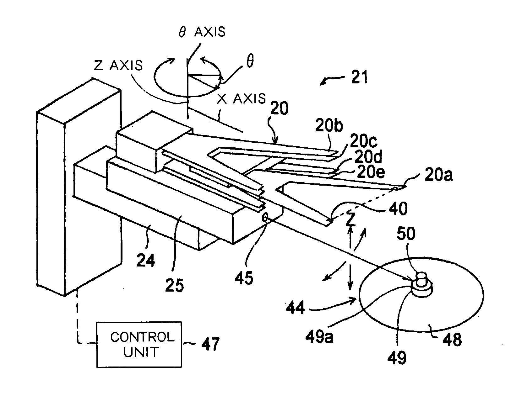
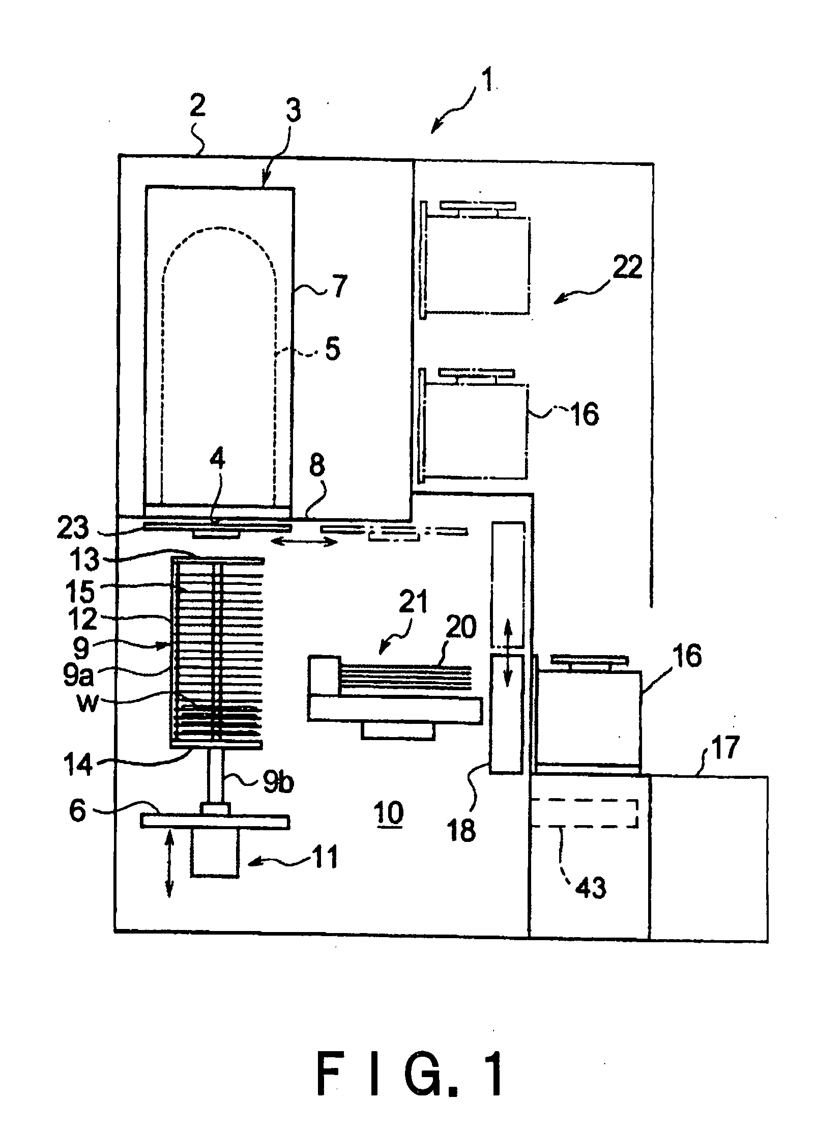
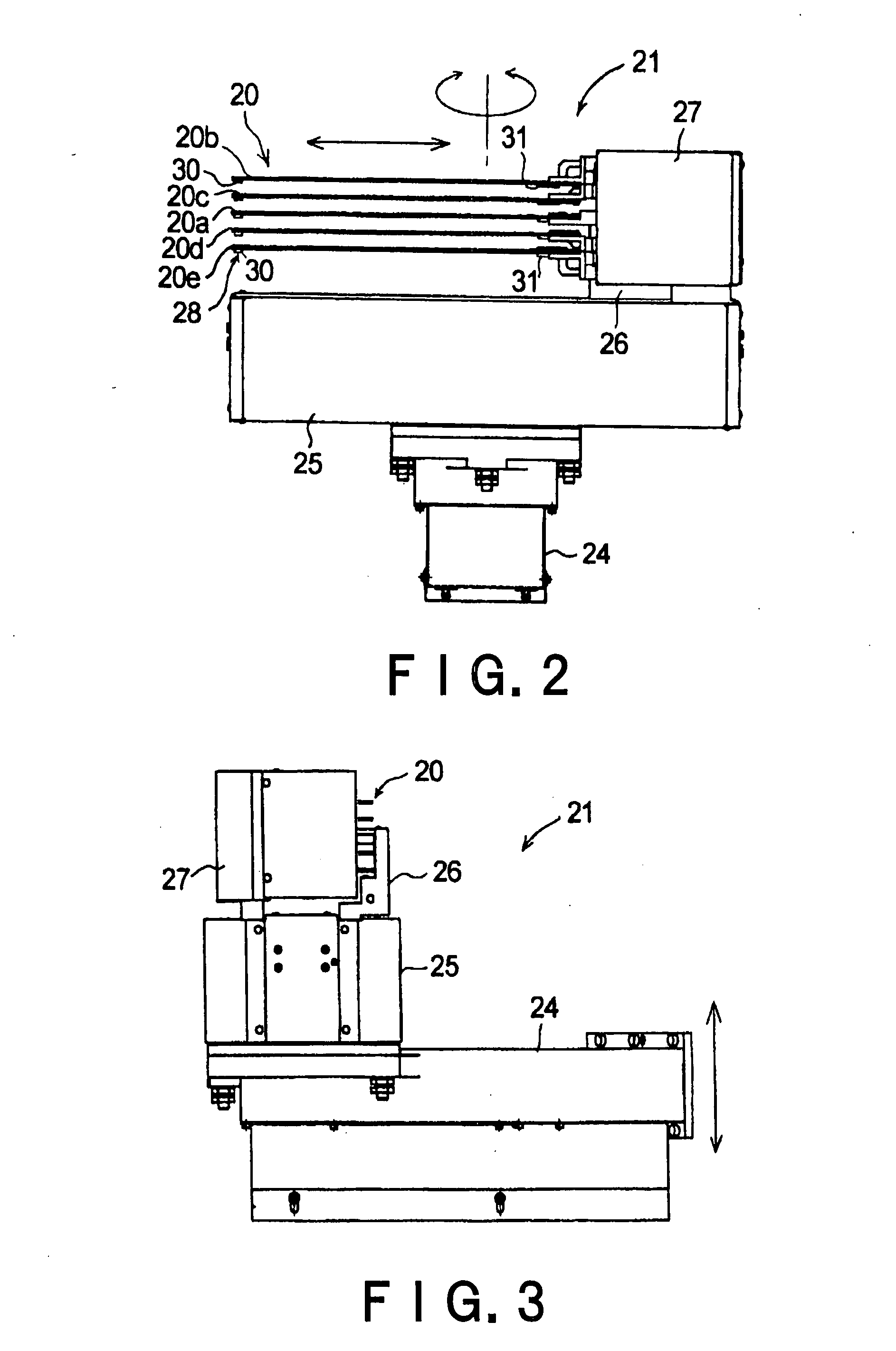
[0044] The best mode for carrying out the invention will be described in detail with reference to the accompanying drawings. FIG. 1 is a longitudinal cross-sectional view schematically showing a vertical heat treatment system in one embodiment of the present invention. FIG. 2 is a side view of a transfer mechanism. FIG. 3 is a side view of the transfer mechanism of FIG. 2 viewed from another side. FIG. 4 is a plan view of a substrate support device and related parts of the transfer mechanism.

[0045] As shown in FIG. 1, a vertical heat treatment system 1 includes an enclosure 2 serving as a frame of the system. A vertical heat treatment furnace 3 is provided in the enclosure 2 at an upper part thereof. The heat treatment furnace 3 accommodates process objects (also referred to as “substrates to be processed”) such as semiconductor wafers W each having a shape of a thin circular disk, and performs a predetermined treatment, e.g., a CVD treatment. The heat treatment furnace 3 mainly co...


PUM


Abstract

A transfer mechanism 21 of a vertical heat treatment system 1 includes a base capable of vertical movement and turning movement, and plural substrate support devices, disposed on the base so as to be movable anteroposterior, that hold wafers W. Provided on the base 25 is a first sensor 45 that emits a light beam directed toward a direction in which the substrate support device 20 moves anteroposterior, and detects the target member upon receipt of a reflected light of the light beam. Provided on two tip end portions of the substrate support device 20 is a second sensor 40 that detects the target member upon interruption of a light beam traveling between the tip end portions by the target member. When a target member 44 provided at its specific positions with projections 49 and 50 is placed at a position in a wafer boat 8, the base 25 moves vertically and turns, and the substrate support device 20 moves anteroposterior. The position of the target member, or the transfer target position of the wafer, is automatically detected based on the detection signals of the first sensor 45 and the second sensor obtained at the time and encoder values of drive systems relating to the movement of the base 25 and the substrate support member 20.

Description

TECHNICAL FIELD [0001] The present invention relates to a vertical heat treatment system and an automatic teaching method for a transfer mechanism, and more particularly to a technique of automatic teaching by which the transfer mechanism for transferring process objects automatically finds the operation target point by itself. BACKGROUND ART [0002] A manufacturing process of a semiconductor device includes various process steps that perform various heat treatments, such as an oxidation treatment, a diffusion treatment, a CVD treatment, and an annealing treatment, to process objects, e.g., semiconductor wafers. A vertical heat treatment system capable of heat-treating plural wafers at one time has been used as one of heat treatment systems for performing the foregoing process steps. [0003] The vertical heat treatment system includes: a heat treatment furnace; a holder (also referred to as “wafer boat”) that is loaded and unloaded into and from the heat treatment furnace while the ho...

Claims


Application Information

Patent Timeline
Patent Type & Authority Applications(United States)
IPC IPC(8): G01B11/14B25J9/22B25J9/16B65G49/07G05B19/19G05B19/42H01L21/00H01L21/22H01L21/324H01L21/677H01L21/68H01L21/687
CPCB25J9/163G05B2219/36039G05B2219/37555G05B2219/40519G05B2219/45031H01L21/68707H01L21/67259H01L21/67265H01L21/67757H01L21/67781H01L21/681G05B2219/45063
Inventor ASARI, SATOSHIMIHARA, KATSUHIKOKIKUCHI, HIROSHI
Owner TOKYO ELECTRON LTD
Why Eureka
Try Eureka