Lantern using LEDs and rechargeable solar panel

a solar panel and led light technology, applied in the field of solar rechargeable lanterns, can solve the problems of shortening the life of the battery, and affecting the charge capacity of the battery

Inactive Publication Date: 2007-11-29
LEDTRONICS
View PDF6 Cites 29 Cited by
  • Summary
  • Abstract
  • Description
  • Claims
  • Application Information

AI Technical Summary

Benefits of technology

[0010]The present invention provides a solar rechargeable lantern that utilizes light emitting diodes (LEDs) as the light source. A light-emitting diode (LED) is a diode that emits light when a current passes through it. A diode is a semiconductor device through which current can pass in only one direction. LEDs are more efficient, last longer, and are more durable than incandescent lamps and are approximately 16 times more efficient at producing light than incandescent lamps. While an incandescent lamp may produce light for 750 to 2,000 operating hours, of continuous use, many LEDs can produce light for 100,000 hours of continuous use. The lantern comprises a base member having a rechargeable battery positioned therein, a solar panel for charging the battery when necessary and a printed circuit board mounted in the base member having a plurality of LED arrays mounted thereon, the battery in turn being connected to the LED arrays. When the lantern is switched on, the user can select low or high illumination as required. In the preferred embodiment, the LED array comprises twelve parallel rows of LEDs, each row having two LEDs.
[0012]The present invention thus provides a solar rechargeable lantern that is less costly to maintain than lanterns currently available by using LEDs as the light source.

Problems solved by technology

Unfortunately, solar-powered lanterns suffer several disadvantages.
First, when the battery fully discharges, the life of the battery is shortened.
Second, full discharge degrades the battery, causing the battery to hold less charge each cycle.
Third, the lights within the solar lanterns oscillate or flicker when the battery is weak.
Although the '367 patent addressed the battery problems in a solar rechargeable lantern, the standard problems of using conventional incandescent bulbs as the illumination source still remain.
While the technology underlying the use of incandescent lights is familiar, there are a number of shortcomings that make their use less than ideal.
For example, the incandescent light sources adapted for use in a solar rechargeable lantern typically have a short life expectancy.
Thereafter, the light sources must be replaced, thereby incurring maintenance costs related to labor, replacement parts, and inventory overhead and storage.
Thus, wasted power is expended in the emission of unusable light, which consequently increases the probability of heat damage to the surrounding components and housing structure.

Method used


Image

  • Lantern using LEDs and rechargeable solar panel
  • Lantern using LEDs and rechargeable solar panel
  • Lantern using LEDs and rechargeable solar panel

Examples


Embodiment Construction

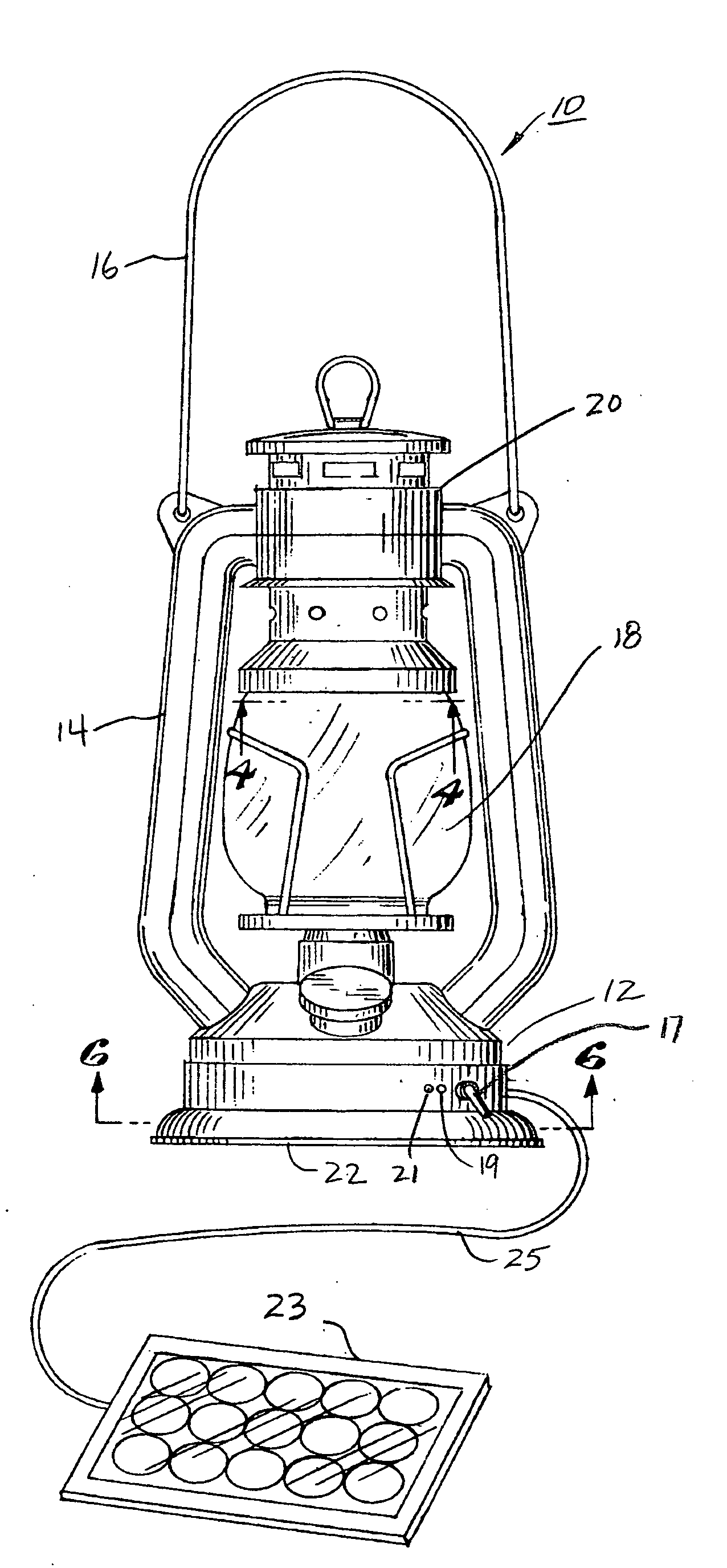
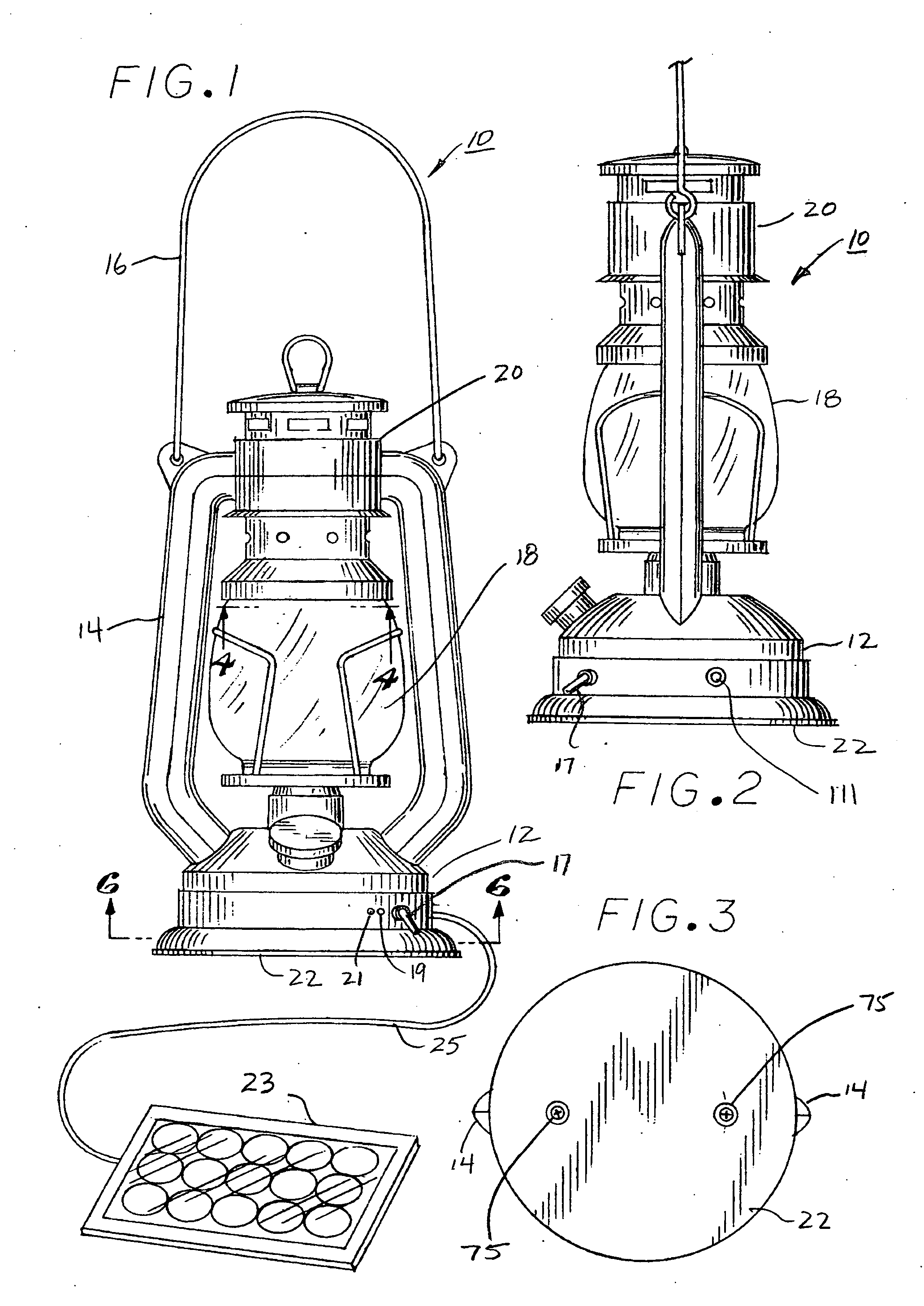
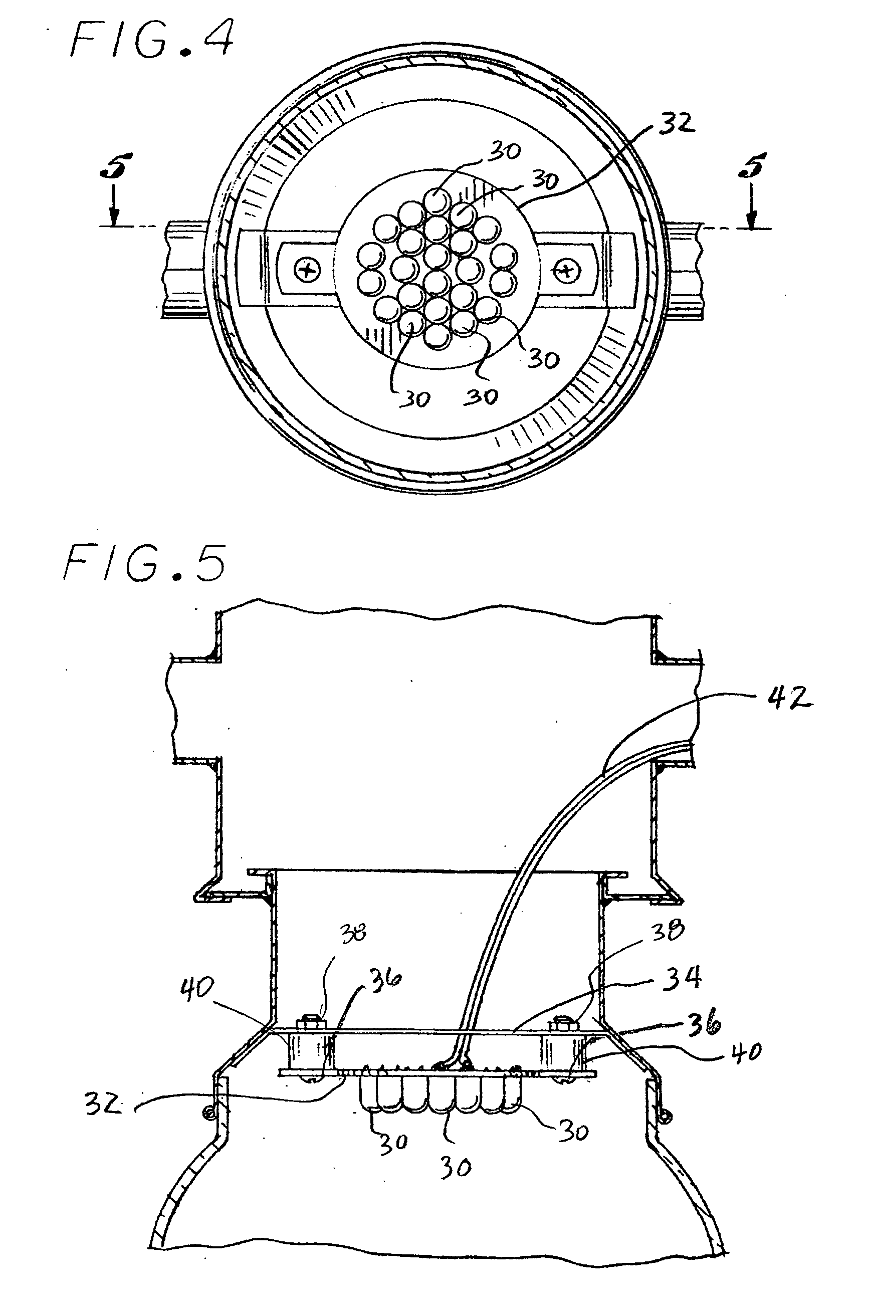
[0023]Referring new to FIGS. 1-3, the modified solar lantern 10 of the present invention is illustrated. Lantern 10 comprises a base portion 12, support structure 14, handle 16, switch 17, transparent envelope 18, and cover portion 20 and bottom surface 22. In addition, solar panel 23 is coupled to base portion 12 via lead 25 when the lantern battery is to be recharged. Although not shown in FIG. 2, lead 25 enters base portion 12 through connector / switch 111. Lantern 10 is conventional except for the modifications set forth in FIGS. 4-9 as will now be described. In particular, FIGS. 4 and 5 illustrate a plurality of light emitting diodes (LEDs) 30 supported on printed circuit board (PCB) 32. PCB 32 in turn is mounted to base plate 34 via screws 36 and nuts 38. Spacers 40 separate PCB 32 from plate 34. Cable 42 couples the power from battery pack 60 (FIG. 9) to the PCB 32 which, in turn, provides power to the LEDs 30.

[0024]When lantern 10 is ready for use, switch 17 is moved either t...


PUM


Abstract

A solar rechargeable lantern that utilizes light emitting diodes (LEDs) as the light source. The lantern comprises a base member having a rechargeable battery positioned therein, a light emitting portion, a solar panel connected to the battery and a printed circuit board mounted in the light emitting portion and having a plurality of LED arrays mounted thereto, the battery in turn being connected to the LED arrays. A controller is provided to control the charge applied to the battery by the solar panel and to monitor the charge status of the battery. The LED array comprises twelve parallel rows of LEDs, each row having a plurality of serially connected LEDs.

Description

BACKGROUND OF THE INVENTION[0001]1. Field of the Invention[0002]The present invention relates to a solar rechargeable lantern using LEDs for illumination.[0003]2. Description of the Prior Art[0004]Battery powered lanterns are well known in the prior art and are used as portable light sources for a wide variety of work and leisure activities. Such lanterns typically include a base and a fixture mounted on the base. One or more incandescent light bulbs are supported within the fixture, and a battery is contained within the base to power the bulbs.[0005]Solar-powered lanterns were developed to eliminate the need to replace conventional batteries prematurely and / or the need to carry extra batteries. These solar-powered lanterns include a rechargeable battery in the base and a separate solar panel that can be connected to the lantern to recharge the battery. Unfortunately, solar-powered lanterns suffer several disadvantages. First, when the battery fully discharges, the life of the batte...

Claims


Application Information

Patent Timeline
Patent Type & Authority Applications(United States)
IPC IPC(8): F21L4/00
CPCF21L4/00H02J7/355F21Y2101/02F21S9/032F21Y2115/10H02J7/35
Inventor LODHIE, PERVAIZVINOYA, LEI U.BROWN, EMERY A.
Owner LEDTRONICS
Why Eureka
Try Eureka