
Cylinder-piston arrangement

a technology of cylinders and pistons, applied in the direction of pumps, mechanical equipment, liquid fuel engines, etc., can solve the problems of high wear and tear, achieve the effect of improving the guidance of the piston, reducing wear and noise, and increasing the tightness of the entire arrangemen

Inactive Publication Date: 2007-11-29
PFEIFFER VACUUM GMBH
View PDF7 Cites 9 Cited by
  • Summary
  • Abstract
  • Description
  • Claims
  • Application Information

AI Technical Summary

Benefits of technology

[0009] The guide member takes over the mechanical load applied to the seal and which is produced by the oscillating movement that periodically is superimposed on the linear movement, and which is particularly pronounced in the cusp points. As a result of reduced load, the service life of the seal increases. Simultaneously, the guide member reduces noise of the cylinder-piston arrangement.
[0017] A particular simple and favorable assembly and, thereby, an easy replacement of the component is insured when the seal and the guide member are formed integrally as a one-piece component. In this way, the costs are reduced as a result of reduction of costs of materials and reduced manufacturing time.

Problems solved by technology

During a lasting operation, an L-shaped seal is subjected to large loads which could lead to a high wear that is incompatible with high requirements to endurance characteristics of such a seal.

Method used


Image

  • Cylinder-piston arrangement
  • Cylinder-piston arrangement
  • Cylinder-piston arrangement

Examples


Embodiment Construction

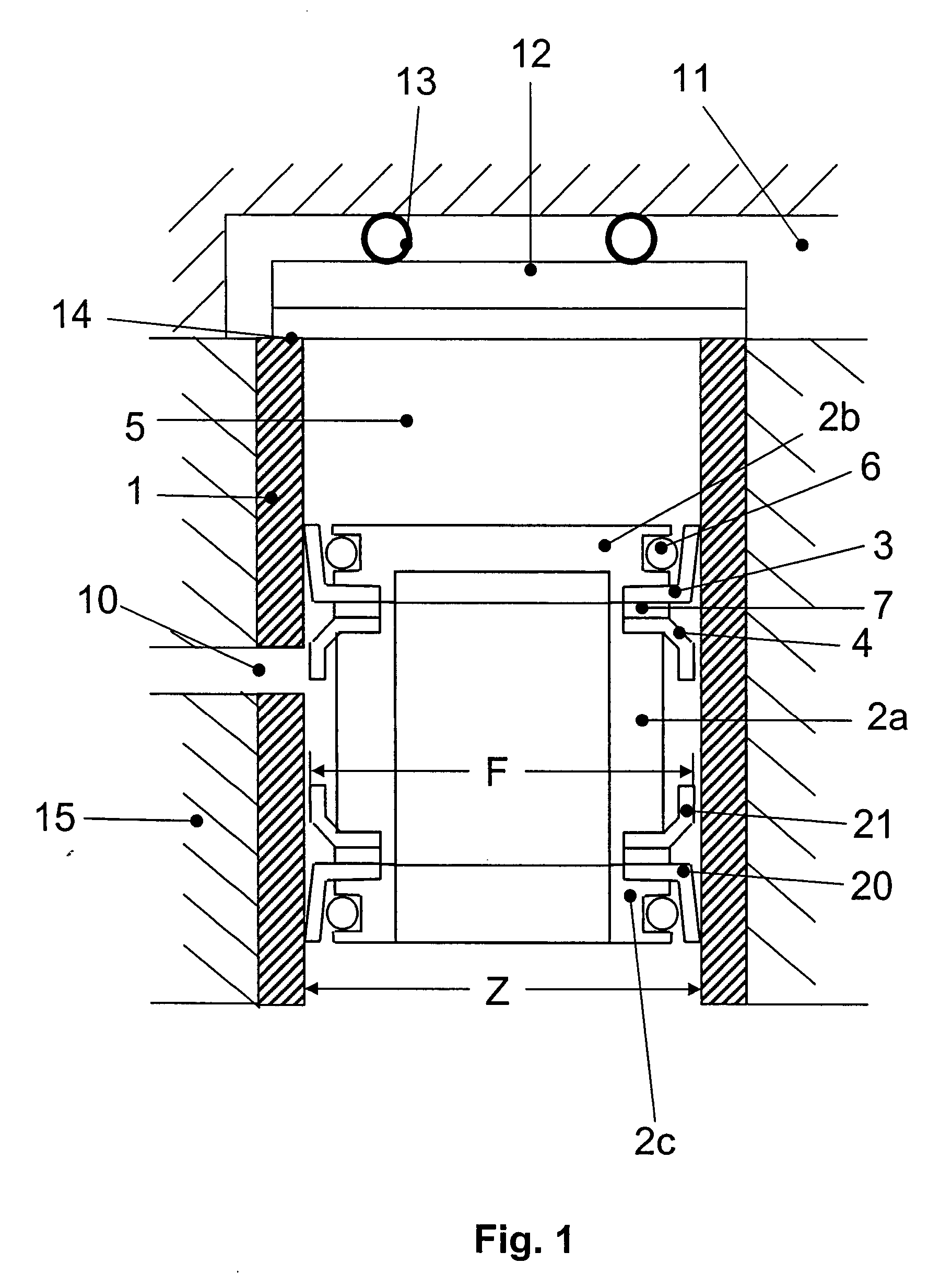
[0024] A cylinder-piston arrangement of a piston vacuum pump, a cross-sectional view of which is shown in FIG. 1, includes a cylinder 1 located in a housing 15 of the pump, and a piston reciprocating in the cylinder 1. As a result of reciprocation of the piston, the volume of the compression chamber 5, which is defined by the cylinder, periodically increases and decreases. A cusp point of the reciprocating movement of the piston, further “a lower cusp point” is characterized by the gas suction process. To this end, there is provided, in cylinder wall, an opening 10 or a plurality of openings communicating with a common inlet channel. The other cusp point, further “an upper cusp point,” is characterized by a gas expelling process. To this end, the piston is displaced in the cylinder so far that the valve cover 12 is lifted from the valve seat 14 and the counter-biasing force of the valve spring 13 is overcome. The compressed gas is then expelled through the gas outlet 11.

[0025] In t...


PUM


Abstract

A sealing arrangement which is designed for a cylinder-piston arrangement of a reciprocating piston vacuum pump for sealing a gap between a cylinder wall and a piston displaceable in the cylinder, includes at least one L-shaped annular seal having one of its leg secured on the piston for providing a static sealing, and its another free leg adjoining the cylinder wall for providing a dynamic sealing, and an annular guide member arranged on the piston between the piston and the cylinder on a side of the seal remote from a compression chamber of the pump.

Description

BACKGROUND OF THE INVENTION [0001] 1. Field of the Invention [0002] The present invention relates to a cylinder-piston arrangement, in particular, to a cylinder-piston arrangement for a reciprocating piston vacuum pump, and more specifically, to a sealing arrangement for a cylinder-piston arrangement of a reciprocating piston vacuum—pump for sealing a gap between a cylinder wall and a piston displaceable in the cylinder, which sealing arrangement includes at least one L-shaped annular seal having one of its legs secured on the piston for providing a static sealing, and its another free leg adjoining the cylinder wall for providing a dynamic sealing [0003] 2. Description of the Prior Art [0004] Since several years, reciprocating piston vacuum pumps have successfully be used as so-called “dry forevacuum pumps.” They find application primarily there where forevacuum, which is free from working fluid, e.g., oil, must be produced because a return flow of working fluid into a recipient ca...

Claims


Application Information

Patent Timeline
Patent Type & Authority Applications(United States)
IPC IPC(8): F04B35/00
CPCF04B37/14F04B53/143F04B39/0005
Inventor CROMM, THOMASSACHS, RONALDZABESCHEK, STEFAN
Owner PFEIFFER VACUUM GMBH
Features
  • Generate Ideas
  • Intellectual Property
  • Life Sciences
  • Materials
  • Tech Scout
  • Unparalleled Data Quality
  • Higher Quality Content
  • 60% Fewer Hallucinations
Learn More