Method For Treatment Of A Fluid Quantity Including Chemical Reacting Means Such As Combustible Materials And A Catalytic Device

a technology of combustible materials and liquids, which is applied in the direction of exhaust treatment, chemical/physical/physicochemical processes, pipe heating/cooling, etc., can solve the problems of significant disadvantage in the connection of electric coils and the disadvantage of electric energy use, and achieve the effect of optimizing cleaning abilities and more price efficient catalytic devices

Inactive Publication Date: 2007-11-29
RECCAT
View PDF2 Cites 5 Cited by
  • Summary
  • Abstract
  • Description
  • Claims
  • Application Information

AI Technical Summary

Benefits of technology

[0094] In an aspect of the invention, said combined carrier means are positioned in continuation of each other through one or more of said at least one passage sections. Hereby it is possible to establish enhanced devices with the advantages of all the types of carrier means.
[0095] In an aspect of the invention, said catalytic material includes metal or metal alloys from the Platinum metal group such as Platinum (Pt), Palladium (Pl), Rhodium (Rh) or combinations hereof. Hereby it is possible to create catalytic devices with optimal cleaning abilities for fluids such as exhaust gases from internal combustion engines.
[0096] In an aspect of the invention, said catalytic material includes metal oxides such as Gold (Au), Platinum (Pt), Silver (Ag), Aluminium (Al), Lead (Pb), Zirconium (Zr), Copper (Cu), Cobalt (Co), Nickel (Ni), Iron (Fe), Cerium (Ce), Chrome (Cr), Tin (Sn), Manganese (Mn) and Rhodium (Rh) Oxides or combinations hereof. The use of metal oxides as catalytic material makes it possible to create more price efficient catalytic devices.

Problems solved by technology

However, an inlet temperature of 200° C. does not necessarily result in a maximum temperature of 400° C. as the temperature at that time is too low for the reactions to take place and the catalyst will be wholly or partly inactive.
However, the heat exchange is not enough to achieve satisfying and stabile temperature conditions inside the catalyst in the heating-up periods and thus, the catalyst comprises temperature regulating means in opposite ends of the container.
The means may for example be electric coils connected to an electric power supply positioned outside the catalyst with the disadvantage of the electric energy use.
Further, the connection for the electric coils is a significant disadvantage due to the price, complexity and vulnerability of the coils and the connections.

Method used


Image

  • Method For Treatment Of A Fluid Quantity Including Chemical Reacting Means Such As Combustible Materials And A Catalytic Device
  • Method For Treatment Of A Fluid Quantity Including Chemical Reacting Means Such As Combustible Materials And A Catalytic Device
  • Method For Treatment Of A Fluid Quantity Including Chemical Reacting Means Such As Combustible Materials And A Catalytic Device

Examples


first embodiment

[0228] In a first embodiment that preferably is used in an application involving a gas engine e.g. in connection with a combined power and heat plant, the plant may have a nominal electric effect of 30 kW.

[0229] The length X is approximately 1.0 meter and the height or diameter Y is approximately 0.3 meter. The UHC value (unburned hydrocarbon) is between 3 and 8% of the firing rate to the engine.

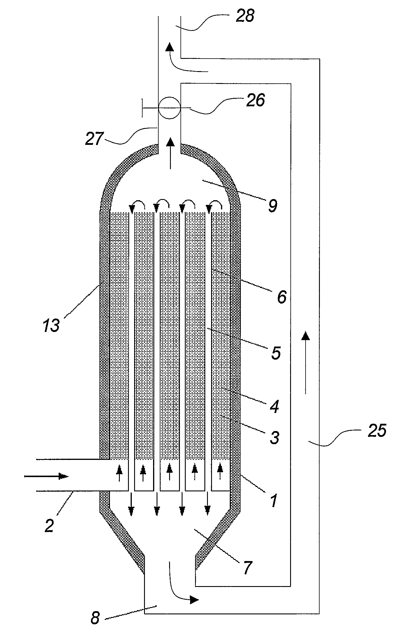
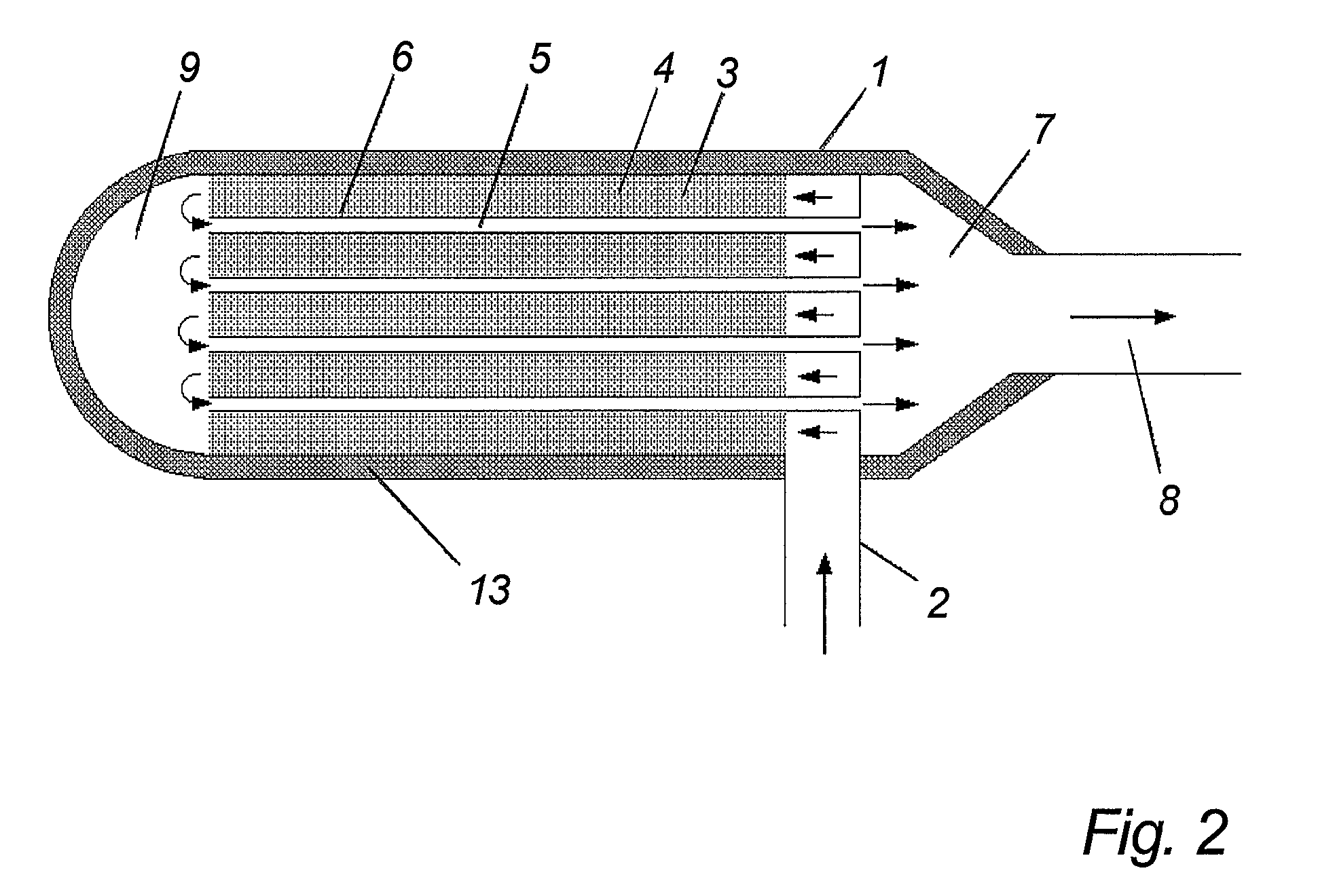
[0230] An application with a gas engine may in a preferred embodiment include a catalytic device with at least 50 pipes in a passage section as illustrated in FIGS. 2, 3, 4, 6, 12, 13 or 14. The diameter of the pipes is approximately 6 to 8 millimeters.

second embodiment

[0231] In a second embodiment that preferably is used in an application involving a gas engine e.g. in connection with a combined power and heat plant, the plant may have a nominal firing rate of 800 kW.

[0232] The length X is approximately 1.2 meter and the height or diameter Y is approximately 1.0 meter. The UHC value (unburned hydrocarbon) is between 3 and 8% of the firing rate to the engine.

[0233] An application with a gas engine may in a preferred embodiment include a catalytic device with at least 200 pipes in a passage section as illustrated in FIGS. 2, 3, 4, 6, 12, 13 or 14. The diameter of the pipes is approximately 8 to 12 millimeters.

third embodiment

[0234] In a third embodiment that preferably is used in an application involving an internal petrol fuelled combustion engine e.g. in connection with vehicles.

[0235] The length X is approximately 0.2 to 0.4 meter and the height or diameter Y is approximately 0.2 meter.

[0236] The UHC value (unburned hydrocarbon) is between 0.5 and 5% of the firing rate to the petrol combustion engine. The value can in a preferred embodiment be raised to approximately 5 to 10% in order to achieve higher temperatures inside the catalytic device by burning further hydrocarbons inside the device. Higher temperatures in the catalytic device mean that catalytic material is saved. Higher values than 10% of the firing rate will affect the efficiency of the petrol combustion engine.

[0237] An application with a petrol combustion engine may in a preferred embodiment include a catalytic device with at least 50 pipes in a passage section as illustrated in FIGS. 2, 3, 4, 6, 12, 13 or 14.


PUM


Abstract

The invention relates to a method for treatment of a fluid quantity including chemical reacting means such as combustible materials above a certain minimum quantity in a catalytic device (1). The method comprises the steps of entering said fluid quantity into the catalytic device (1) through an inlet (2), controlling the temperature in one or more passage sections (3, 5) of said catalytic device (1) including at least one reaction passage section (4), by heat transferring, and emitting the treated fluid quantity from the catalytic device through an outlet (28). The invention also relates to a catalytic device and uses of the method and the catalytic device.

Description

BACKGROUND OF THE INVENTION [0001] The invention relates to a method for treatment of a fluid quantity including chemical reacting means such as combustible materials and a catalytic device according to the preamble of claim 13 and uses hereof. [0002] Most of the known catalysts for cleaning of exhaust gasses from internal combustion engines contain no internal heat exchange. This means that the maximum temperature in the catalyst depends on the inlet temperature in said catalyst. If the unburned gas components by combustion e.g. can increase the temperature in the catalyst by 200° C. an inlet temperature of 300° C. will result in a maximum temperature of 500° C., an inlet temperature of 400° C. will result in a maximum temperature of 600° C., etc. However, an inlet temperature of 200° C. does not necessarily result in a maximum temperature of 400° C. as the temperature at that time is too low for the reactions to take place and the catalyst will be wholly or partly inactive. [0003]...

Claims


Application Information

Patent Timeline
Patent Type & Authority Applications(United States)
IPC IPC(8): F01N3/10B01J19/00F01N3/035F01N3/20F01N3/28F01N13/14F16L53/00
CPCF01N3/035F01N3/2006F01N3/2013F01N3/2046Y02T10/26F01N13/14F01N2240/02F01N2610/03F01N3/2889Y02T10/12
Inventor RASMUSSEN, NIELS
Owner RECCAT
Why Eureka
Try Eureka