Silent chain transmission device

a transmission device and chain technology, applied in the direction of driving chains, belts/chains/gearrings, chain elements, etc., can solve the problems of increased difficulty in link plate manufacturing and chain assembly, inability to achieve a large reduction of engagement noise, and inability to achieve good suppression of vibration noise, etc., to achieve the effect of reducing cyclic engagement noise and being easy to manufactur

Inactive Publication Date: 2007-11-29
TSUBAKIMOTO CHAIN CO
View PDF4 Cites 8 Cited by
  • Summary
  • Abstract
  • Description
  • Claims
  • Application Information

AI Technical Summary

Benefits of technology

[0019]Furthermore, since the inner flanks of the first (“A” type) link plates begin to engage an involute sprocket tooth earlier than an outer flanks of the preceding link plates, the arrangement of the first (“A” type) and second (“B” type) link plates influences the engagement of inner and outer flanks of the first link plates and the outer flanks of the second link plates. As a result, various engagement patterns can be established with only two kinds of link plates, and the link plates can be easily manufactured and assembled into a chain capable of achieving a significant reduction in cyclic engagement sounds.

Problems solved by technology

However, when the silent chain is operated at high speed, vibration due to a polygonal movement of the chain is generated as the chain engages with a sprocket, and until now it has not been possible to achieve good suppression of vibration noise resulting from polygonal movement.
Another troublesome problem in the manufacture of a silent chain was that the chain is composed of two kinds of link plates, so that the link plates have two different rack pitches.
Consequently, cyclic engagement sounds could not be dispersed sufficiently to achieve a large reduction in engagement noise.
Thus, in order to disperse cyclic engagement sounds, a greater number of different kinds of link plates was needed, resulting in increased difficulties in manufacture of the link plates and in the assembly of the chain.

Method used


Image

  • Silent chain transmission device
  • Silent chain transmission device
  • Silent chain transmission device

Examples


Embodiment Construction

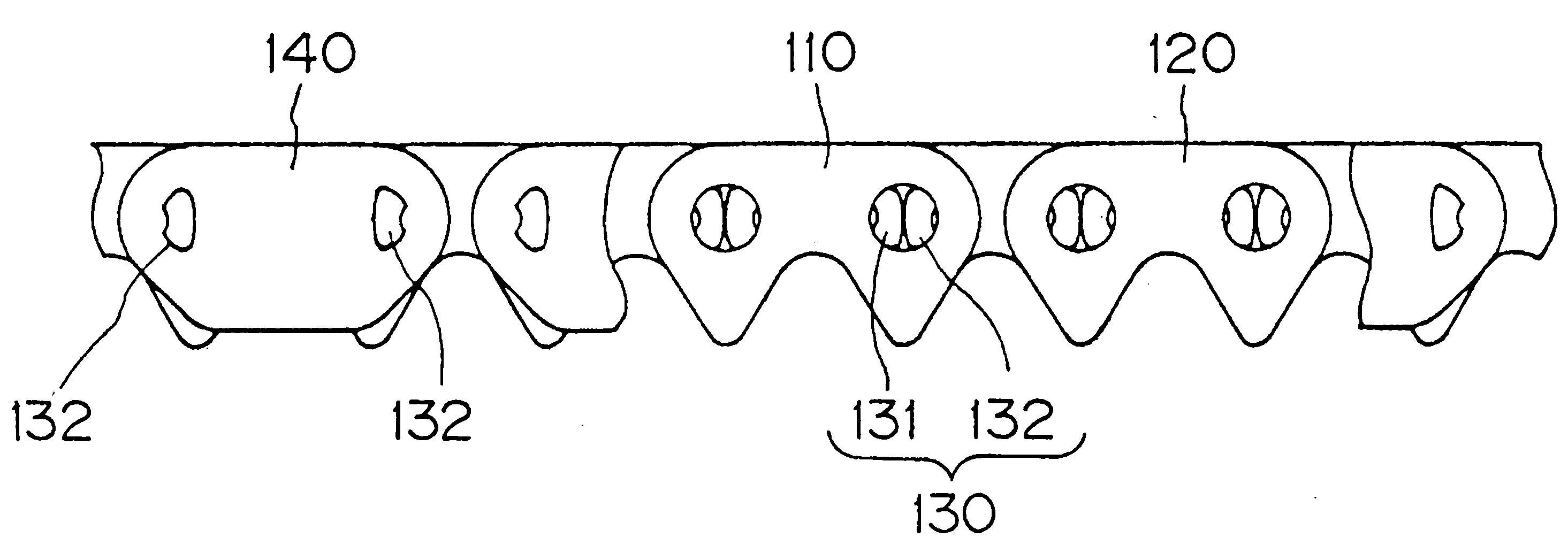
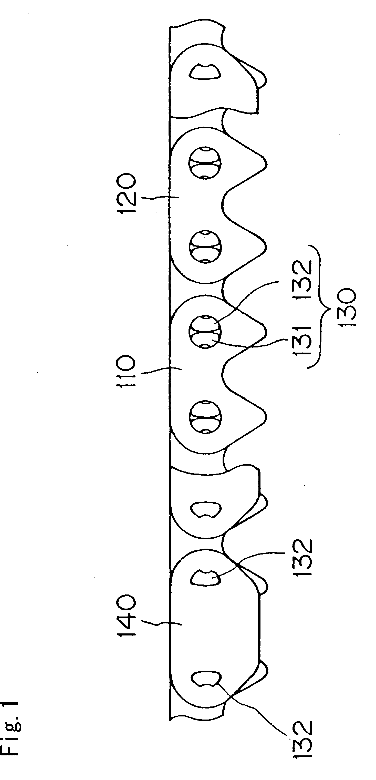
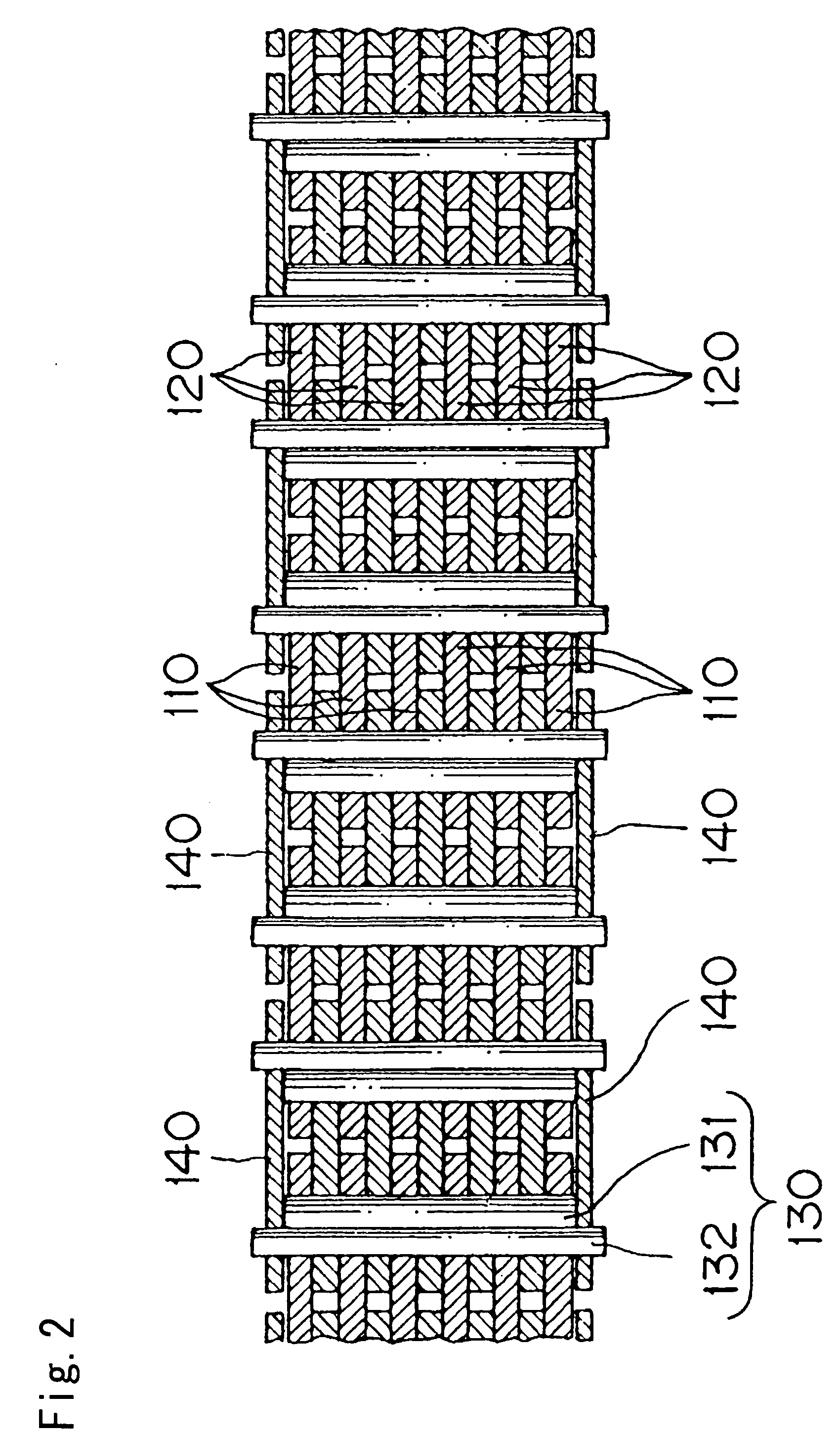
[0028]As shown in FIGS. 1 and 2, the silent chain transmission device comprises a silent chain in which first, or “A” type, link plates 110 and second, or “B” type, link plates 120 are mixed along the longitudinal direction of the chain. Interleaved rows, each preferably consisting of either “A” type or “B” type link plates, are connected to one another by connecting pins 130, each preferably composed of a rocker pin 132 and a joint pin 131. The chain is wound on a sprocket (not shown in FIGS. 1 and 2) for the transmission of power in a mechanism such as the transfer mechanism in a four wheel drive vehicle.

[0029]In addition to the “A” and “B” type link plates, which have teeth, the chain may also include toothless guide plates 140 for keeping the chain aligned with the sprockets by engagement with the sides of the sprocket teeth. Pins 132, which are the longer of the pins of which the connecting pins 130 are composed, are fixed to the guide plates 140 by caulking or other suitable m...


PUM


Abstract

A silent chain transmission utilizes two different kinds of link plates. In a first kind of link plate, the inner flank pitch line is farther than the outer flank pitch line from the chain pitch line. In a second kind of link plate the inner flank pitch line is closer than the outer flank pitch line from the chain pitch line. Every four successive links includes at least one link composed of one type of link plate and at least one link composed of the other type of link plate.

Description

CROSS-REFERENCE TO RELATED APPLICATION[0001]This application claims priority on the basis of Japanese patent application 2006-143168, filed May 23, 2006. The disclosure of Japanese application 2006-143168 is hereby incorporated by reference.FIELD OF THE INVENTION[0002]This invention relates to a silent chain transmission device, and more specifically, it relates to a silent chain transmission device of the kind used, for example, in the transfer mechanism of a four-wheel drive vehicle.BACKGROUND OF THE INVENTION[0003]Silent chains are commonly used for power transmission in motor vehicles, motorcycles, and the like. A silent chain has comprises a number of link plates, each having a pair of teeth and a pair of pin holes. The plates are stacked in rows that extend widthwise of the chain. The plates of adjacent rows are interleaved, and the interleaved rows of plates are connected to each other by connecting pins that extend through the pin holes.[0004]Sounds, referred to as “pitch so...

Claims


Application Information

Patent Timeline
Patent Type & Authority Applications(United States)
IPC IPC(8): F16G13/06
CPCF16G13/04
Inventor MORIMOTO, TAKAYUKIOHARA, HITOSHIKOMADA, MINORUKOTANI, KAZUFUMIHAMAGUCHI, SHUUJI
Owner TSUBAKIMOTO CHAIN CO
Why Eureka
Try Eureka