Introducer Sheath and Method for Making

a technology of introduction sheath and inserting sheath, which is applied in the direction of catheter, etc., can solve the problems of affecting the ability of the inserting sheath to freely deliver other devices, such as stents, normal stent size and the ability of the inserting sheath to be compromised, and the structure may be too thick-walled, so as to achieve enhanced torqueability

Inactive Publication Date: 2007-11-29
COOK INC
View PDF12 Cites 35 Cited by
  • Summary
  • Abstract
  • Description
  • Claims
  • Application Information

AI Technical Summary

Benefits of technology

[0011] The present invention addresses the problems of the prior art by providing a low profile introducer sheath having enhanced torqueability, and a method for making the introducer sheath.

Problems solved by technology

If an introducer sheath kinks, the lumen size and the ability of the sheath to freely deliver other devices, such as stents, will normally be compromised.
For example, utilizing both reinforcements in an intermediate layer results in a structure that may be too thick-walled for some proposed uses, hi addition, the wire or monofilament layers are susceptible to interfering with each other, in which case the resulting device would have neither good torqueability nor good kink resistance.
If the sheath is much larger than about 0.010 inch (0.254 mm), the entry site may be of a size to cause damage to the vessel wall, and / or it may cause difficulties in the manipulation of the sheath or catheter through the anatomy.
In addition, if a combined braid and coil layer is provided, this layer is difficult to over coat properly with the thermoplastic layer.
If the melted outer layer cannot flow through the wires of both the braid and sheath, there may be insufficient bonding of the outer layer to the inner liner.
This may result in the dislodgement of one layer from the other during use of the device.
However, once the tip of this sheath has been placed in the vasculature, the torque control of the sheath can be less than optimal, and it can be difficult to rotationally control the direction of the tip in some applications.

Method used


Image

  • Introducer Sheath and Method for Making
  • Introducer Sheath and Method for Making
  • Introducer Sheath and Method for Making

Examples


Embodiment Construction

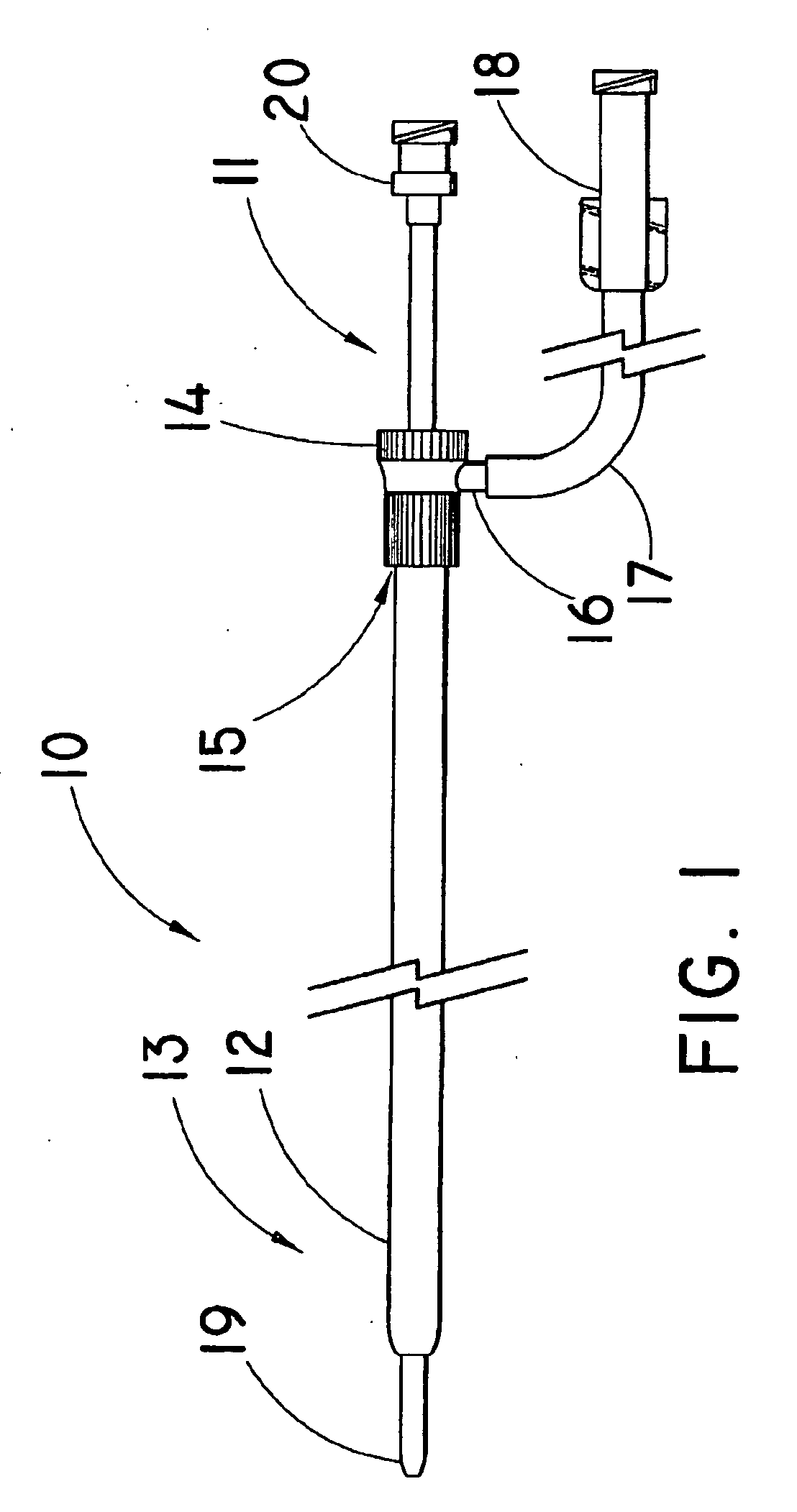
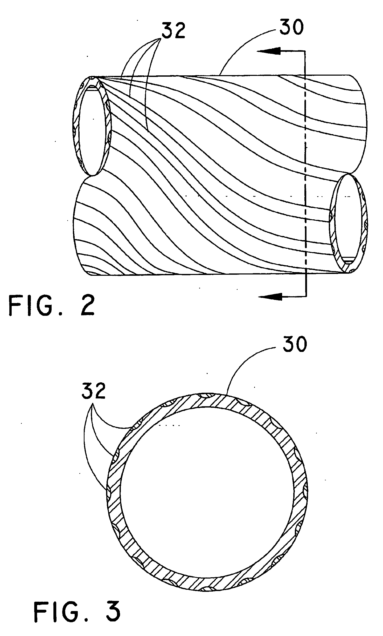
[0021] For the purposes of promoting an understanding of the principles of the invention, reference will now be made to the embodiments illustrated in the drawings, and specific language will be used to describe the same. It should nevertheless be understood that no limitation of the scope of the invention is thereby intended, such alterations and further modifications in the illustrated device, and such further applications of the principles of the invention as illustrated therein being contemplated as would normally occur to one skilled in the art to which the invention relates.

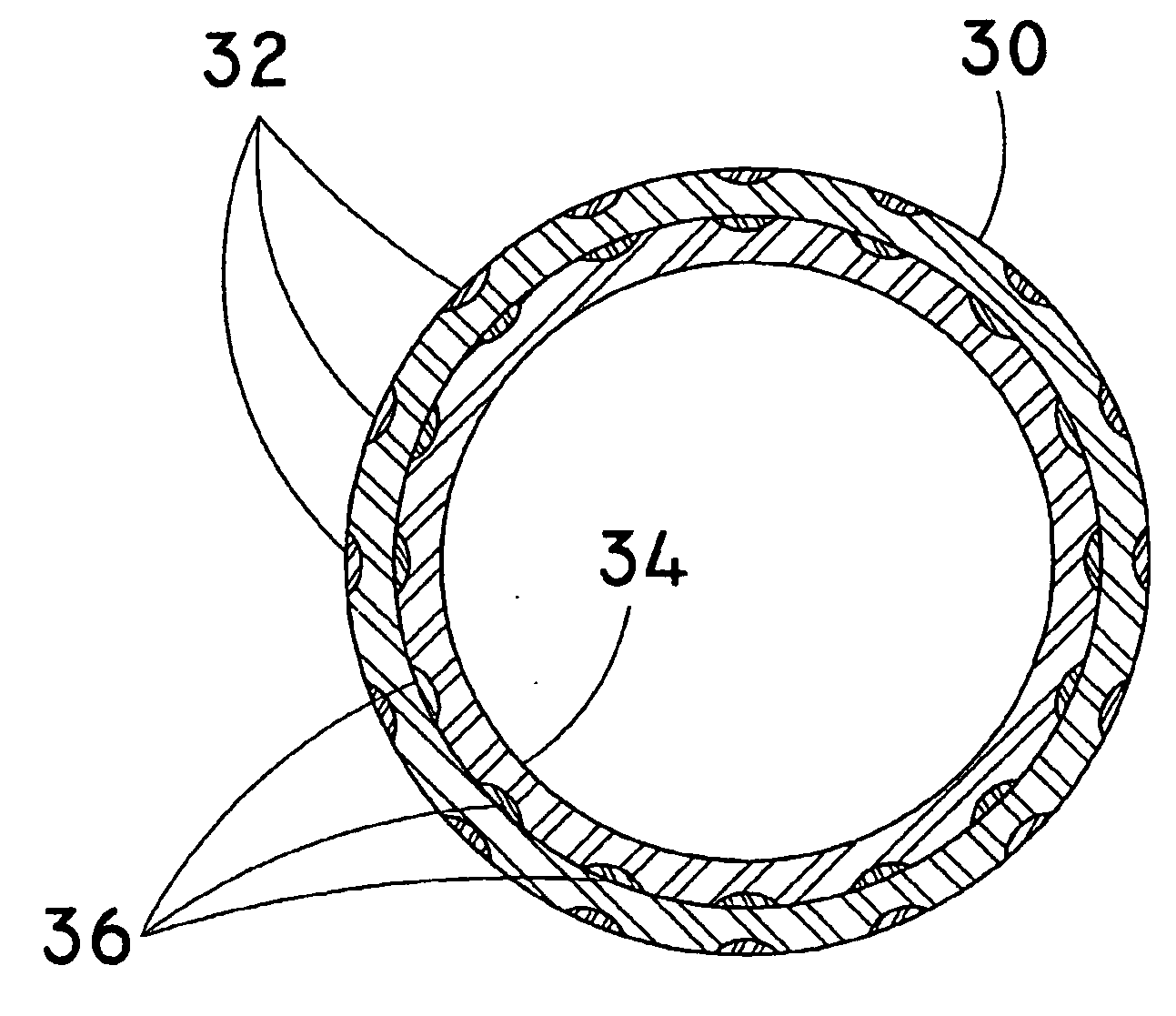
[0022] In the following discussion, the terms “proximal” and “distal” will be used to describe the opposing axial ends of the introducer sheath, as well as the axial ends of various component features. The term “proximal” is used in its conventional sense to refer to the end of the sheath (or component thereof) that is closest to the operator during use of the sheath. The term “distal” is used in its conve...


PUM

PropertyMeasurementUnit
sizeaaaaaaaaaa
diameteraaaaaaaaaa
diameteraaaaaaaaaa

Abstract

An introducer sheath and a method of manufacturing an introducer sheath. The introducer comprises a first polymeric sleeve having a first striped extrusion arranged in a generally helical pattern along the first sleeve. A second polymeric sleeve is positioned over and bonded to the first polymeric sleeve, the second polymeric sleeve comprising a second striped extrusion that is arranged in a generally helical pattern along the second sleeve. The first and second polymeric sleeves are axially aligned such that the second striped extrusion is superposed over the first striped extrusion to define a generally braid-like configuration. The introducer sheath can optionally include an inner liner disposed within a lumen of the first polymeric sleeve, and / or a coil fitted over the inner liner, such that the first polymeric sleeve is bonded to the inner liner between turns of the coil.

Description

BACKGROUND [0001] 1. Technical Field [0002] The present invention relates to an apparatus, such as an introducer sheath, for use in the placement of a medical interventional device, and to a method for making the apparatus. [0003] 2. Background Information [0004] Percutaneous entry devices, referred to herein as “introducer sheaths”, are typically used to introduce medical interventional devices, such as balloon angioplasty catheters and stents, into the vasculature. Such introducer sheaths are typically thin-walled tubular devices that are fitted to an inner dilator for percutaneous placement over a wire guide. Current introducer sheaths are often extruded from compositions such as PTFE or PFEP. Other introducer sheaths are typically formed as composite constructions consisting of an inner liner formed of a low friction, lubricous material such as PTFE, an intermediate reinforcing layer consisting of a braid or a coil, and an outer layer formed of a thermoplastic compound such as a...

Claims


Application Information

Patent Timeline
Patent Type & Authority Applications(United States)
IPC IPC(8): A61M25/16
CPCA61M25/0012A61M25/0662B29C47/064B29C47/0023B29C47/0014B29C48/05B29C48/09B29C48/19B29C48/20
Inventor OSBORNE, THOMAS A.
Owner COOK INC
Why Eureka
Try Eureka