Filter device for embolic protection systems

a filter device and protection system technology, applied in the field of embolic protection systems and methods, can solve the problems of emboli not always fully vaporized, may enter the bloodstream, and the patient's release into the circulatory system can be extremely dangerous, and achieve the effect of a higher degree of confidence in the efficient operation of the filtering system

a filter device and protection system technology, applied in the field of embolic protection systems and methods, can solve the problems of emboli not always fully vaporized, may enter the bloodstream, and the patient's release into the circulatory system can be extremely dangerous, and achieve the effect of a higher degree of confidence in the efficient operation of the filtering system

US20070276429A1Inactive Publication Date: 2007-11-29ABBOTT CARDIOVASCULAR

Image

  • Filter device for embolic protection systems
  • Filter device for embolic protection systems
  • Filter device for embolic protection systems

Examples


Embodiment Construction

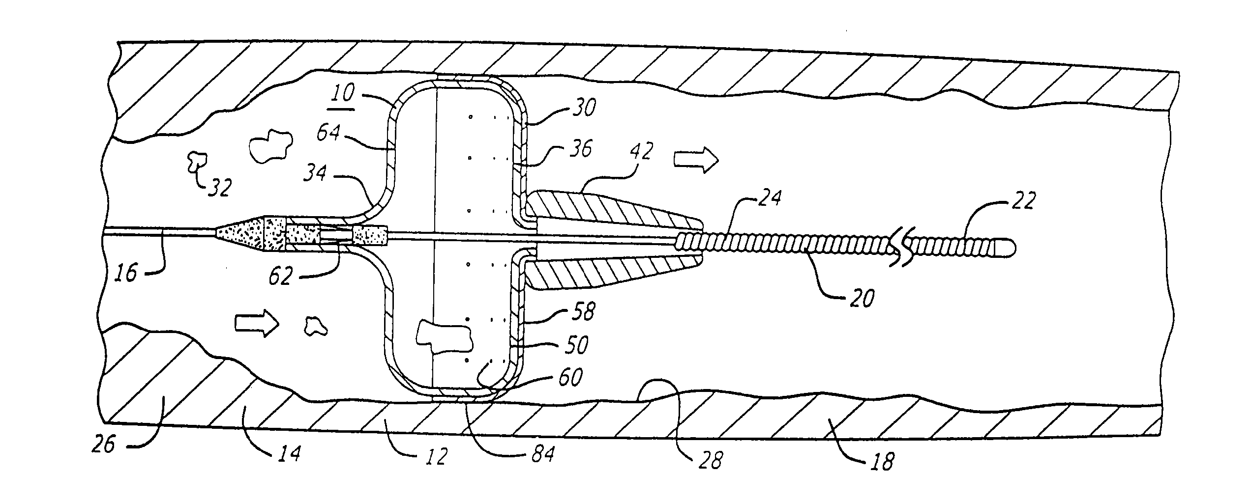
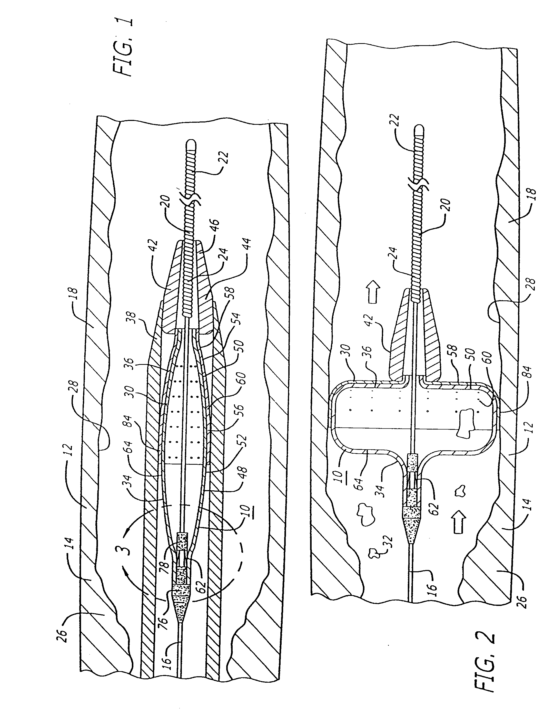
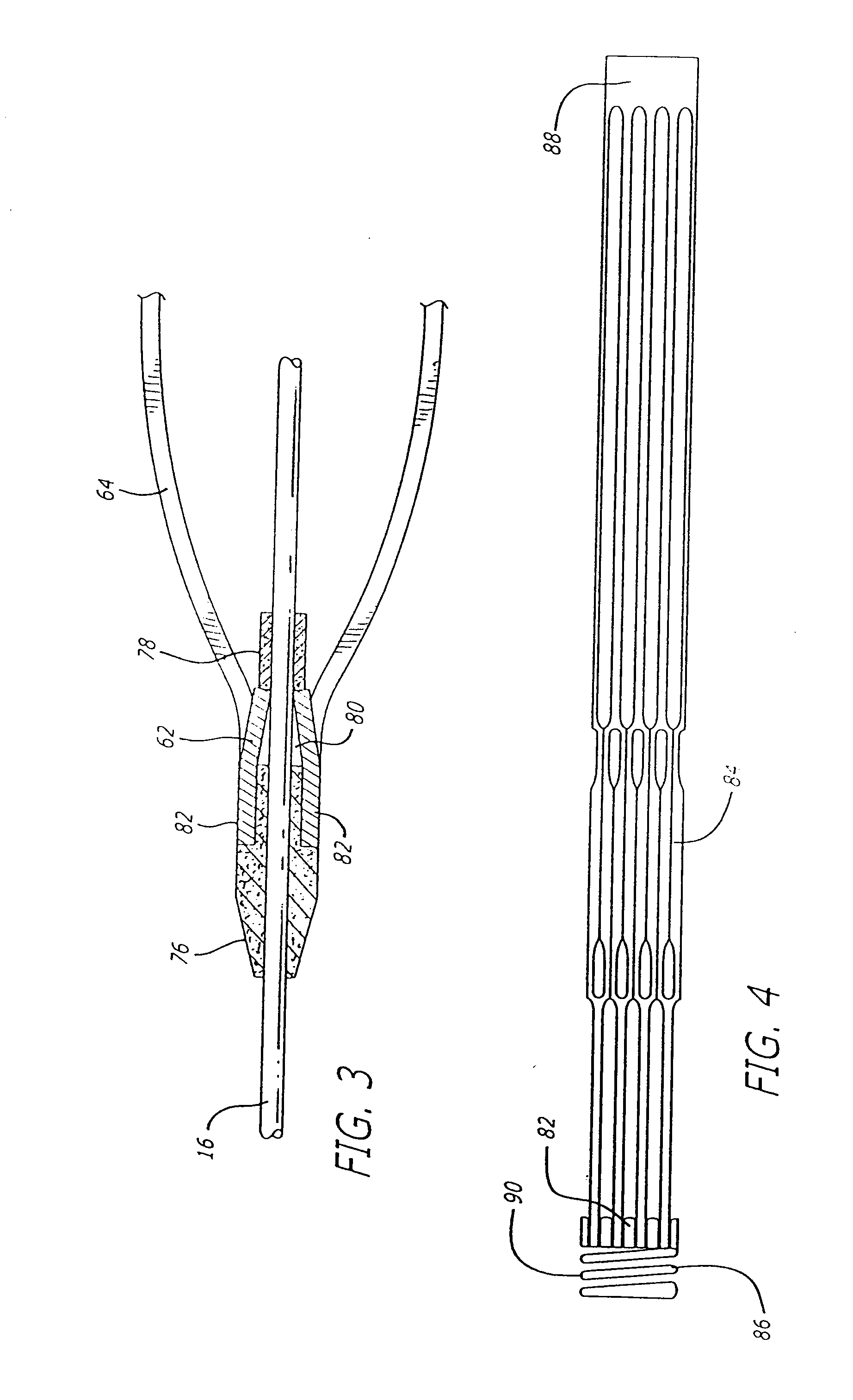
[0025] The present invention is directed to an improved system and method for enabling the capture of embolic material which may be released into the blood vessel during the therapeutic interventional procedure, in an efficient and effective manner. The invention enables a filter device to be snap-fitted to a guide wire for effective and convenient engagement therewith, enables rotational movement of the filter device independent of rotational movement of the guide wire, and inhibits translational movement of the filter device along the guide wire. The present invention is further directed to efficiently providing a reference for positioning the filter device in the patient's anatomy. The filter device is also formed of expandable material, and includes an end thereof which is formed so as to be in tension, enabling a portion of the filter device to be in tension and another portion to be in compression, to aid the filter device in the bending thereof in tortuous vasculature.

[0026]...


PUM


Abstract

A system for enabling the insertion and removal of an embolic protection device, for capturing and retaining embolic debris which may be created during the performance of a therapeutic interventional procedure in a stenosed or occluded region of a blood vessel. The system, in an embodiment thereof, enables the device to be snap-fitted so as to engage the distal end of a guide wire, to provide a reference for positioning the device at a location distal to the interventional procedure site, and to enable an end of the device to be in tension, enabling a portion of the device to be in tension and another portion to be in compression, so as to assist in bending thereof in tortuous vasculature.

Description

CROSS-REFERENCE TO RELATED APPLICATIONS [0001] This is a continuation of Ser. No. 10 / 465,332 filed Jun. 19, 2005, which is a continuation of application Ser. No. 09 / 919,503 filed Jul. 31, 2001, which is a continuation-in-part of application Ser. No. 09 / 896,142 filed on Jun. 29, 2001 the contents of which are hereby incorporated by reference. [0002] This application is a continuation of application Ser. No. 09 / 919,503 filed Jul. 31, 2001 which is a continuation-in-part of application Ser. No. 09 / 896,142 filed on Jun. 29, 2001.BACKGROUND OF THE INVENTION [0003] The present invention relates generally to improvements in embolic protection systems and methods. In particular, it relates to an improved system and method for enabling an embolic protection device to be efficiently and conveniently engaged with the distal end of a guide wire. The system also enables the device to effectively expand against the inner surface of a blood vessel wall, and to seal off the inner surface thereof up...

Claims


Application Information

Patent Timeline
29 Nov 2007
Publication
US20070276429A1
IPC
A61F2/01; A61B17/00; A61B17/22; A61M25/01
CPC
A61F2/013; A61F2002/011; A61F2002/015; A61F2230/008; A61F2230/0006; A61F2230/0065; A61F2002/018; A61F2/011
Inventors
HUTER, BENJAMIN C.; PAPP, JOHN E.