Automotive air-conditioning system

Inactive Publication Date: 2007-12-06
SANDEN CORP
View PDF8 Cites 2 Cited by
  • Summary
  • Abstract
  • Description
  • Claims
  • Application Information

AI Technical Summary

Benefits of technology

[0030]Since the preferable automotive air-conditioning system uses CO2 as refrigerant, it is environmentally friendly. At the same time, the automotive air-conditioning system separates the

Problems solved by technology

Therefore, the automotive air-conditioning system is

Method used


Image

  • Automotive air-conditioning system
  • Automotive air-conditioning system
  • Automotive air-conditioning system

Examples


Embodiment Construction

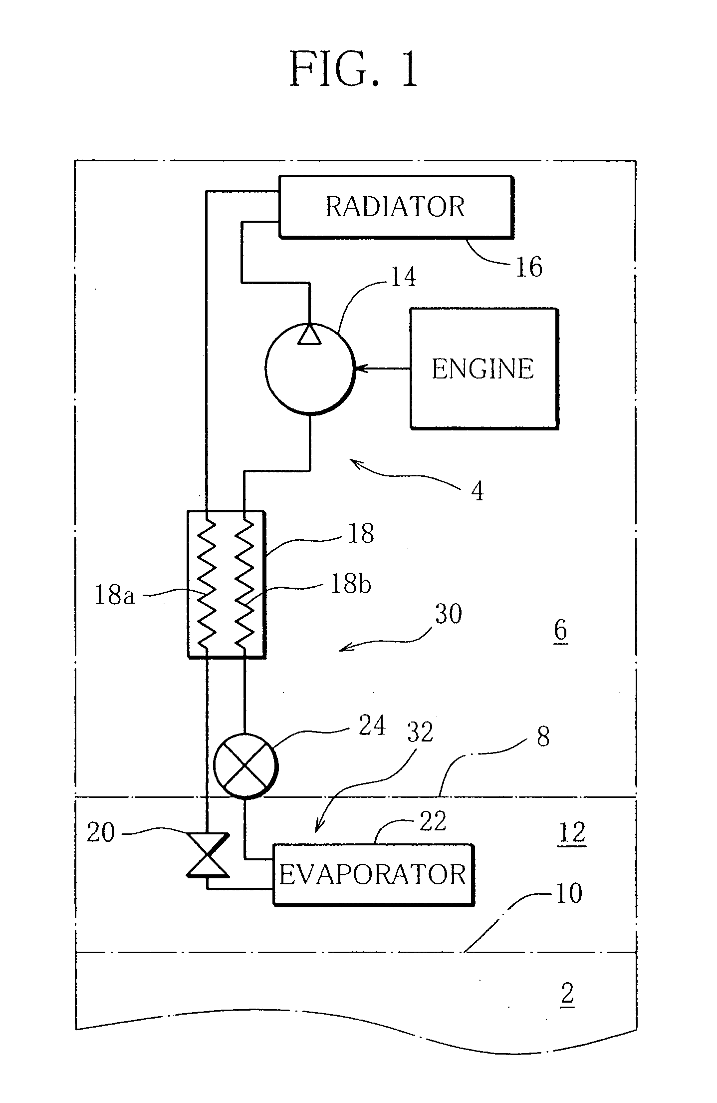
[0036]FIG. 1 schematically shows a refrigeration circuit of an automotive air-conditioning system according to one embodiment. The refrigeration circuit is of a vapor compression type and is used for refrigerating or dehumidifying an air flow that is introduced into a vehicle interior 2.

[0037]The refrigeration circuit has a circulation path 4. CO2 refrigerant (R-744) that is a natural refrigerant circulates through the circulation path 4 while containing a small amount of lubricating oil serving as refrigerating machine oil. The circulation path 4 extends from an engine room 6 through a partition wall 8 to a front portion of the vehicle interior 2. The front part of the vehicle interior 2 is partitioned by an installment panel 10 and serves as an equipment space 12.

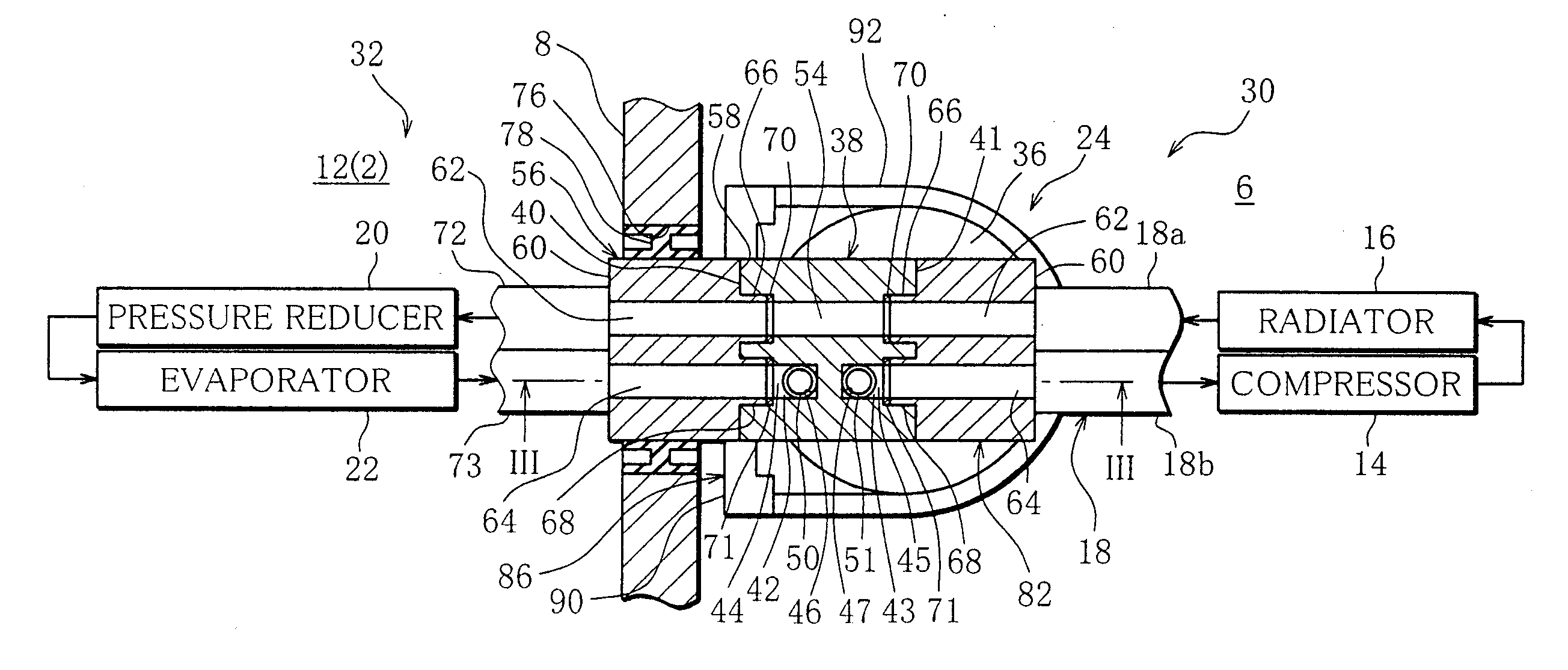
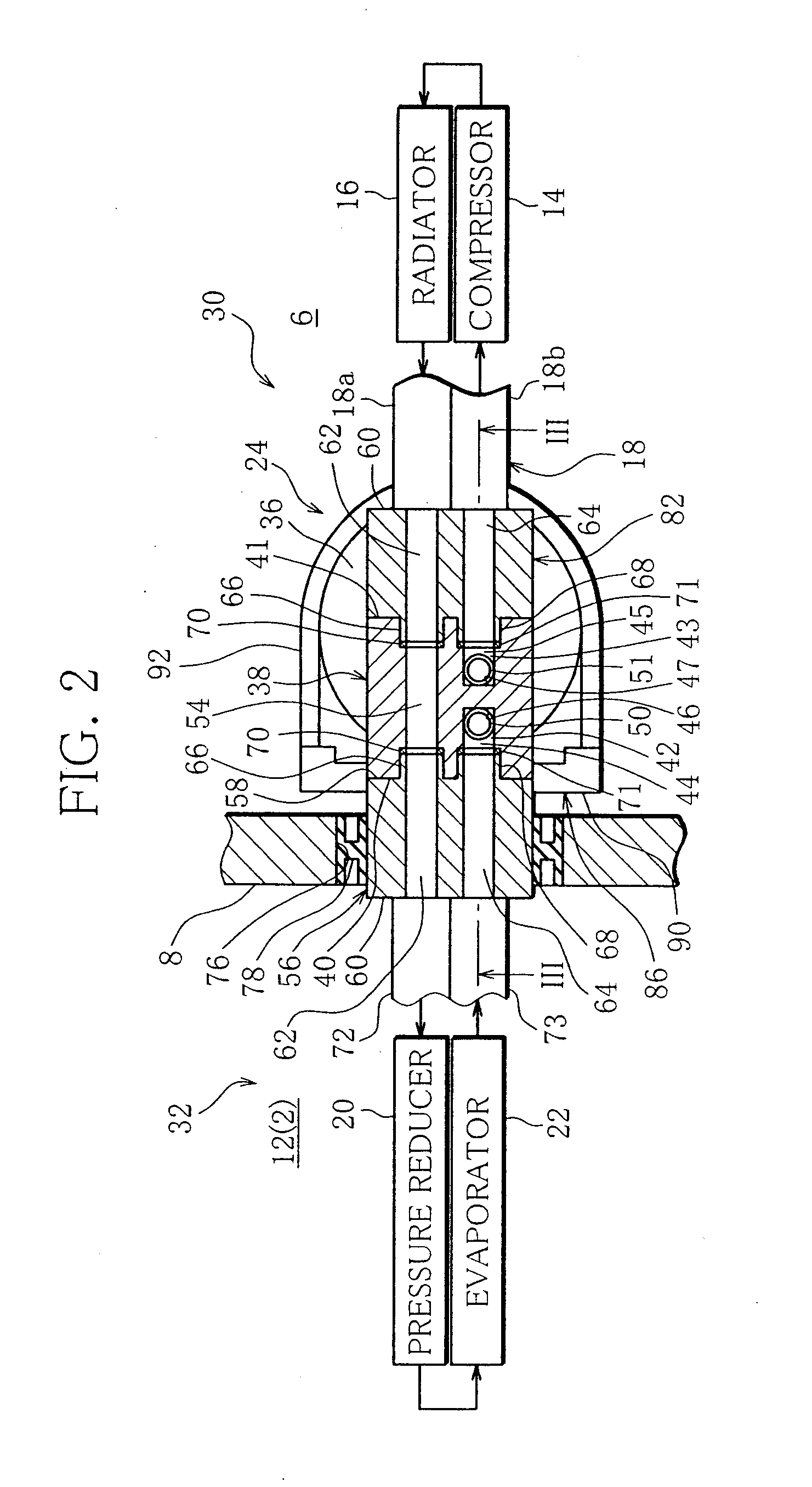
[0038]In the circulation path 4, there are interposed a compressor 14, a radiator (gas cooler) 16, a high-temperature portion 18a of an internal heat exchanger 18, a pressure reducer (expansion valve) 20, an evaporator 22...


PUM


Abstract

An automotive air-conditioning system has a gas-liquid separator, a compressor and a radiator, which are interposed in a first flow channel of a refrigerant which extends within an engine room in the order in the flowing direction of the refrigerant. The system also includes a pressure reducer and an evaporator, which are interposed in a second flow channel of the refrigerant which extends within a vehicle interior in the order in the flowing direction of the refrigerant. The system also has a connecting device disposed near a partition wall that separates the engine room from the vehicle interior. The connecting device circularly connects the first to the second flow channel, and includes a first connecting portion formed at the downstream end of the second flow channel and a second connecting portion that is formed at the inlet of the gas-liquid separator and is connected to the first connecting portion.

Description

BACKGROUND OF THE INVENTION[0001]1. Field of the Invention[0002]The present invention relates to an automotive air-conditioning system.[0003]2. Description of the Related Art[0004]A refrigeration circuit of an automotive air-conditioning system has a circulation path through which a refrigerant circulates. The circulation path includes a first flow channel extending within an engine room and a second flow channel extending within a vehicle interior. The first and second flow channels are circularly connected to each other near a partition wall that separates the engine room from the vehicle interior.[0005]In general, a compressor, a radiator (condenser or gas cooler), a pressure reducer (expansion valve) and an evaporator are interposed in the circulation path in the order named in the flowing direction of the refrigerant.[0006]A gas-liquid separator for separating a gas-phase component and a liquid-phase component contained in the refrigerant is also interposed in the circulation p...

Claims


Application Information

Patent Timeline
IPC IPC(8): F25B43/00F25B41/00
CPCB60H1/00571B60H1/3229F25B9/008F25B2500/18F25B43/006F25B2309/061F25B40/00
Inventor TSUBOI, MASATOSUZUKI, KENICHIMATSUMOTO, YUUICHI
Owner SANDEN CORP
Why Eureka
Try Eureka