Method for forming an optical converter

a fiber optic and faceplate technology, applied in the direction of bundled fibre light guides, semiconductor devices, solid-state devices, etc., can solve the problems of increasing the overall requirements for using fiber optic faceplates as optical converters for electronic image display, increasing the complexity of tiling arrangements, and reducing the cost of fabrication. , the effect of easy fabrication

Inactive Publication Date: 2007-12-06
EASTMAN KODAK CO
View PDF10 Cites 5 Cited by
  • Summary
  • Abstract
  • Description
  • Claims
  • Application Information

AI Technical Summary

Benefits of technology

[0015] It is an advantage of the present invention that it is easily adaptable for fabrication of a wide range of fiber-optic faceplate formats and shapes, at low cost relative to conventional methods.
[0016] It is a further advantage of the present invention that it relaxes dimensional constraints on fiber optic strands themselves for faceplate fabrication. The present invention allows fabrication of faceplates having thinner depths than are currently available using conventional methods.
[0017] It is yet a further advantage of the present invention that it affords considerable flexibility for providing a tapered fiber faceplate arrangement, allowing variable fiber-to-fiber spacing for both sides of a fiber faceplate.

Problems solved by technology

A recognized problem for displays using these components relates to inherent dimensional limitations of the electronic image-forming components themselves.
However, the overall requirements for using fiber optic faceplates as optical converters for electronic image display are more demanding, particularly when used with LCD, LED, OLED, or PLED devices.
It can be appreciated that tiling arrangements introduce even more complexity into the faceplate fabrication problem.
As a result, fiber optic faceplates suitable for electronic image display continue to be costly and difficult to fabricate.
However, neither the '578 , '812, nor '731 patents provide a suitable solution for optical fiber faceplate fabrication.
However, such methods are highly dependent on the uniformity of fiber dimensions.
Additional tolerance error is due to winding tension differences as the fiber strands are wound about the drum.
More significantly, however, the methods of the '578, '812, and '731 patents do not provide a way to vary the center-to-center spacings between fibers, both at input and at output ends of the fiber bundle.
This adds cost and complexity to the fabrication process.

Method used


Image

  • Method for forming an optical converter
  • Method for forming an optical converter
  • Method for forming an optical converter

Examples


Embodiment Construction

[0036] The present description is directed in particular to elements forming part of, or cooperating more directly with, apparatus in accordance with the invention. It is to be understood that elements not specifically shown or described may take various forms well known to those skilled in the art.

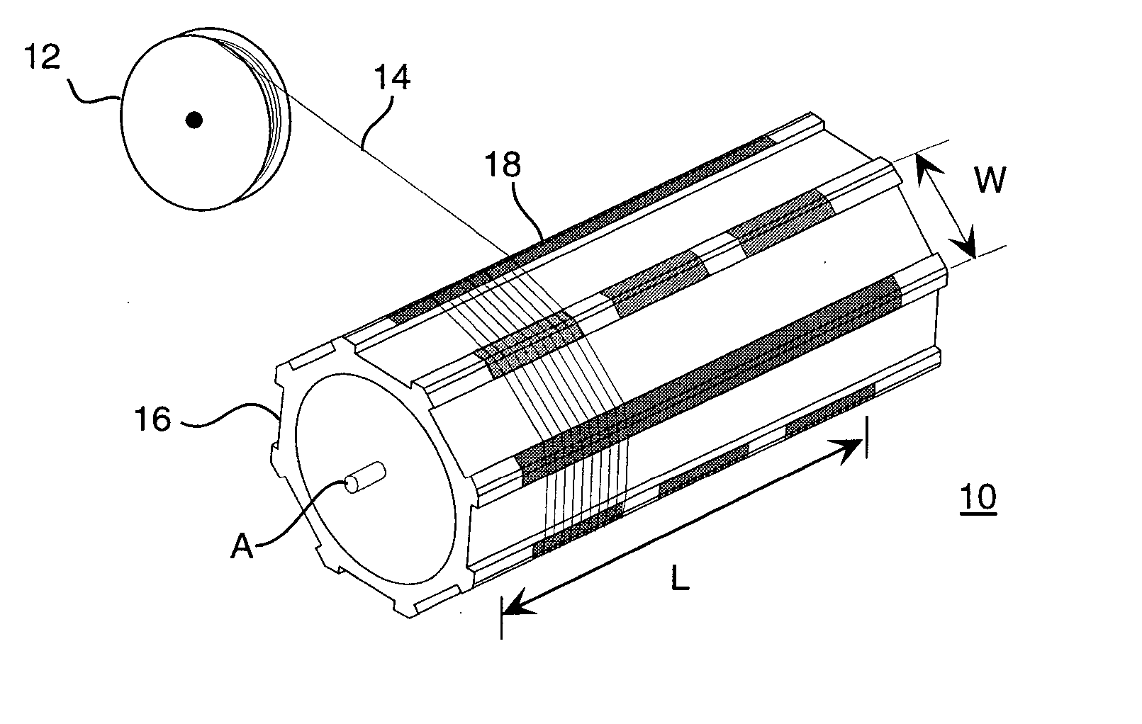
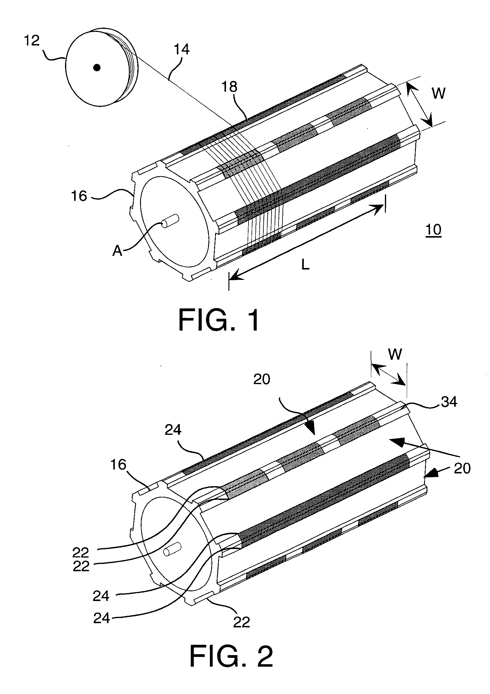
[0037] In order to understand the particular apparatus and methods applied using the present invention for fabricating fiber optic faceplates, it is most instructive to look first at the basic structural building block fabricated using the apparatus of the present invention and used for assembling the fiber optic faceplate. Referring to FIG. 12, there is shown a portion of a ribbon structure 40 which serves as a novel elemental component for fiber optic faceplate fabrication. Ribbon structure 40 comprises an array of optical fiber segments 50, generally disposed parallel to each other, for guiding light from an input edge 46, over width W, to an output edge 48. Fiber segments 50 on input...


PUM

PropertyMeasurementUnit
widthaaaaaaaaaa
lengthaaaaaaaaaa
adhesiveaaaaaaaaaa

Abstract

A fiber optic faceplate fabricated using a series of stacked ribbon structures. Each ribbon structure comprises optical fiber segments that run from an input edge to an output edge with fixed input and output fiber-to-fiber spacing. Input and output edge spacers may be used to provide spacing between stacked ribbon structures. Ribbon structures may be provided individually or as one or more sheets of ribbon structures.

Description

CROSS-REFERENCE TO RELATED APPLICATIONS [0001] This is a divisional of U.S. application Ser. No. 10 / 314,843, entitled “Optical Converter Formed From Flexible Strips,” filed Dec. 9, 2002 by Roger S. Kerr, et al.FIELD OF THE INVENTION [0002] This invention generally relates to fabrication of fiber optic faceplates as optical converters for use in imaging systems and more particularly relates to a fiber optic faceplate fabricated from flexible strips containing multiple light guides. BACKGROUND OF THE INVENTION [0003] One advantage of electronic display systems is the capability to display an image in a variety of formats and sizes. There is particular interest in providing large scale displays, visible to thousands of viewers over considerable distance, such as would be useful for entertainment and advertising. One known method for providing large scale electronic displays is tiling, in which a matrix of smaller displays are linked together to form a larger display surface. [0004] Ima...

Claims


Application Information

Patent Timeline
Patent Type & Authority Applications(United States)
IPC IPC(8): B31C13/00B31C99/00G02B6/06G02B6/04H01L27/32H01L51/52
CPCG02B6/04H01L27/3293H01L51/52Y10T156/1051Y10T156/1015Y10T156/1002H01L51/5262H10K59/18H10K50/80H10K50/85
Inventor KERR, ROGER S.COK, RONALD S.KESSLER, DAVID
Owner EASTMAN KODAK CO
Why Eureka
Try Eureka