Reverse Circulation Pressure Control Method and System

a technology of reverse circulation and control method, which is applied in the direction of wellbore/well accessories, chemistry apparatus and processes, construction, etc., can solve problems such as unbalanced well conditions

Inactive Publication Date: 2007-12-06
BAKER HUGHES INC
View PDF25 Cites 47 Cited by
  • Summary
  • Abstract
  • Description
  • Claims
  • Application Information

AI Technical Summary

Benefits of technology

[0013] Examples of the more important features of the disclosure have been summarized (albeit rather broadly) in order that the detailed description thereof that follows may be better understood and in order that the

Problems solved by technology

In still other embodiments, annulus pressure is decre

Method used


Image

  • Reverse Circulation Pressure Control Method and System
  • Reverse Circulation Pressure Control Method and System
  • Reverse Circulation Pressure Control Method and System

Examples


Embodiment Construction

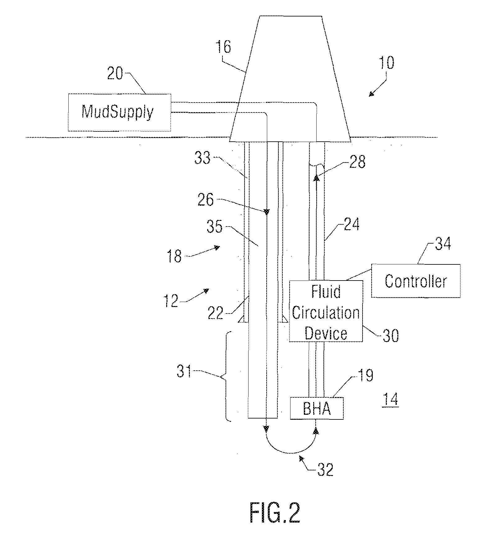
[0034] Referring initially to FIG. 2, there is schematically illustrated a well construction facility 10 for forming a wellbore 12 in an earthen formation 14. The facility 10 includes a rig 16 and known equipment such as a wellhead, blow-out preventers and other components associated with the drilling, completion and / or workover of a hydrocarbon producing well. For clarity, these components are not shown. Moreover, the rig 16 may be situated on land or at an offshore location. In accordance with one embodiment of the present disclosure, the facility 10 includes a fluid circulation system 18 for providing drilling fluid to a downhole tool or drilling assembly 19. One exemplary fluid circulation system 18 includes a surface mud supply 20 that provides drilling fluid into a supply line 22. This drilling fluid circulates through the wellbore 12 and returns via a return line 24 to the surface. For clarity, the downward flow of drilling fluid is identified by arrow 26 and the upward flow ...


PUM


Abstract

A system for reverse circulation in a wellbore include equipment for supplying drilling fluid into the wellbore bit via at least an annulus of the wellbore and returning the drilling fluid to a surface location via at least a bore of a wellbore tubular. The system also includes devices for controlling the annulus pressure associated with this reverse circulation. In one embodiment, an active pressure differential device increases the pressure wellbore annulus to at least partially offset a circulating pressure loss. In other embodiments, the system includes devices for decreasing the pressure in the annulus of the wellbore. For offshore application, annulus pressure is decreased to accommodate the pore and fracture pressures of a subsea formation. In still other embodiments, annulus pressure is decreased to cause an underbalanced condition in the well.

Description

CROSS-REFERENCE TO RELATED APPLICATIONS [0001] This application takes priority from U.S. Provisional Patent Application Ser. No. 60 / 787,128, filed Mar. 29, 2006. This is a continuation-in-part of U.S. patent application Ser. No. 10 / 713,708, filed Nov. 14, 2003, which is now U.S. Pat. No. 7,055,627 which takes priority from U.S. Provisional Patent Application Ser. No. 60 / 428,423, filed on Nov. 22, 2002.BACKGROUND OF THE DISCLOSURE [0002] 1. Field of the Disclosure [0003] This disclosure relates generally to oilfield wellbore drilling systems and more particularly to drilling fluid circulation systems that utilize a wellbore fluid circulation device to optimize drilling fluid circulation. [0004] 2. Background of the Art [0005] Oilfield wellbores are drilled by rotating a drill bit conveyed into the wellbore by a drill string. The drill string includes a drill pipe (tubing) that has at its bottom end a drilling assembly (also referred to as the “bottomhole assembly” or “BHA”) that carr...

Claims


Application Information

Patent Timeline
IPC IPC(8): E21B21/08
CPCE21B21/00E21B2021/006E21B21/08E21B21/085
Inventor KRUEGER, SVENKRUEGER, VOLKERBRUNS, JENSFINCHER, ROGERWATKINS, LARRYARONSTAM, PETERFONTANA, PETER
Owner BAKER HUGHES INC
Why Eureka
Try Eureka