Power conditioning architecture for a wind turbine

a technology of power conditioning architecture and wind turbine, which is applied in the direction of electric generator control, machine/engine, dynamo-electric converter control, etc., can solve the problems of premature failure of the wind turbine, substantial oscillation of the rotor phase current, and stringent demands of the transient, so as to reduce the size of the transient current and torque level

a technology of power conditioning architecture and wind turbine, which is applied in the direction of electric generator control, machine/engine, dynamo-electric converter control, etc., can solve the problems of premature failure of the wind turbine, substantial oscillation of the rotor phase current, and stringent demands of the transient, so as to reduce the size of the transient current and torque level

US20070278797A1Active Publication Date: 2007-12-06WISCONSIN ALUMNI RES FOUND

Image

  • Power conditioning architecture for a wind turbine
  • Power conditioning architecture for a wind turbine
  • Power conditioning architecture for a wind turbine

Examples


Embodiment Construction

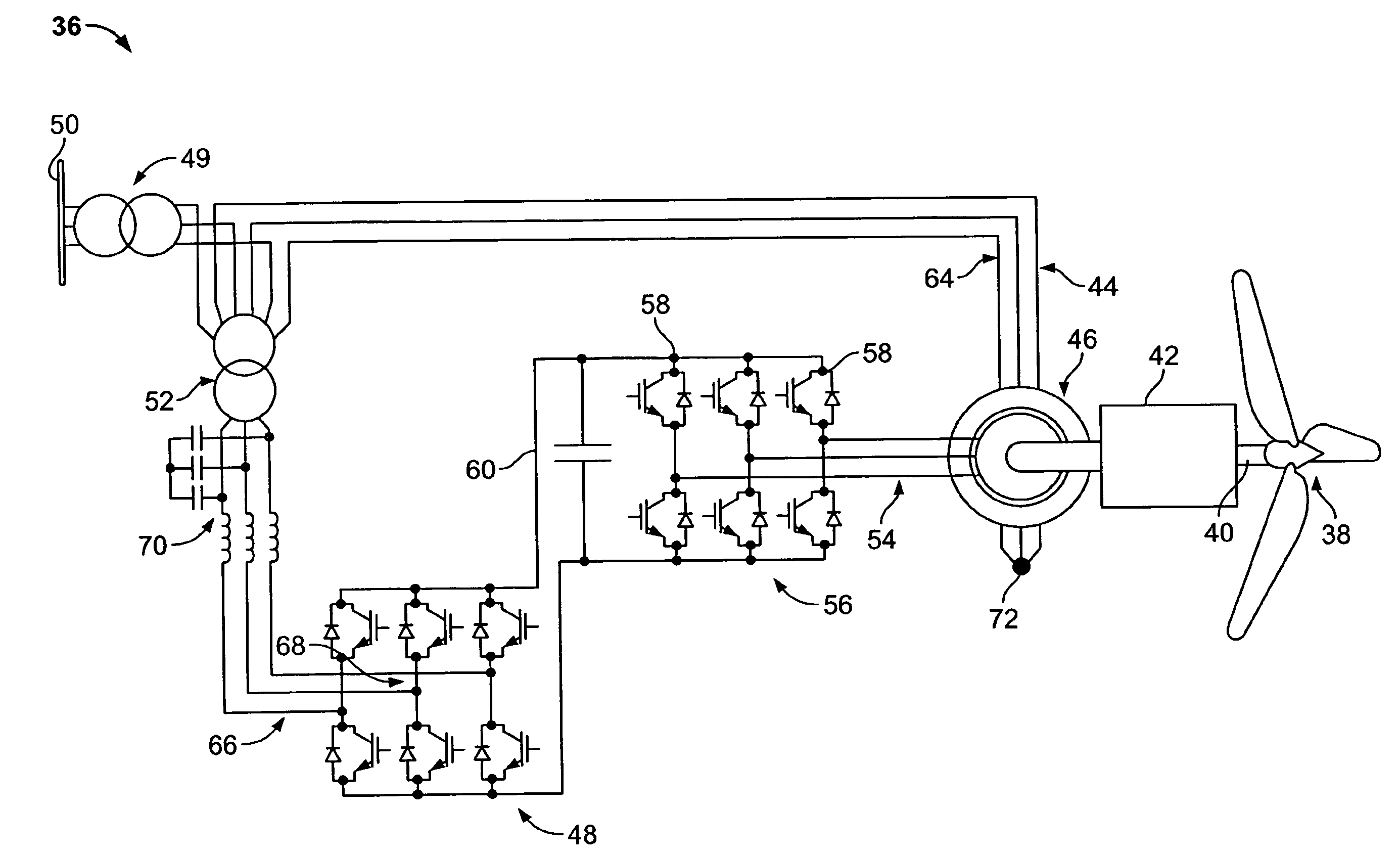
[0043]FIG. 4A schematically shows a stator-side architecture for a DFIG-based wind turbine according to one embodiment of the present disclosure. As illustrated, a SGSC (series grid side converter) behaves as a buffer between a collector, e.g., PCC (point of common coupling), and a DFIG (doubly fed induction generator) thereby decoupling interactions between the PCC and the DFIG. As will be explained in greater detail below, the SGSC is effective in reducing stator flux in the DFIG during voltage disturbances, such as voltage sags, in the PCC.

[0044]FIG. 4B illustrates a wind turbine 36, according to one embodiment of the present disclosure that incorporates a buffer such as that described with respect to FIG. 4A. The wind turbine 36 includes a blade arrangement 38 connected to a rotor 40 that is driven in a computer controlled manner by a gearbox 42. The gearbox 42 is connected to a DFIG circuit 44 through a generator 46. The DFIG circuit 44 has a series grid side converter (SGSC) 4...


PUM


Abstract

A wind turbine 36 has a back-to-back AC / DC / AC power electronic converter chain in which the grid side converter 48 is connected in series with DFIG stator windings 64. The machine side converter 56 is fed from the rotor windings 54 of the DFIG 44. Series connection of the grid side converter 48 enables voltage sag ride-through capability via control of the stator flux.In the event of a grid voltage sag, the series converter allows for a controlled response in the stator flux and electromagnetic shaft torque, protects the machine side converter and enables continued power delivery to the grid.

Description

CROSS-REFERENCE TO RELATED APPLICATION[0001]This application claims the benefit of U.S. Ser. No. 60 / 809,737 filed May 31, 2006, the disclosure of which is incorporated herein by reference.BACKGROUND OF THE INVENTION[0002]1. Field of the Invention[0003]The preferred embodiments are directed to wind turbine generators, and more particularly, electrical architecture for such generators that facilitates operation during grid faults and low voltage events.[0004]2. Description of the Prior Art[0005]Worldwide capacity of wind-powered generators makes up less than 1% of world-wide electricity use. Nevertheless, although still a relatively minor source of electricity for most countries, wind power generation more than quadrupled between 1999 and 2005. For example, wind power is used in large scale wind farms to supply national electrical grids, but is also used in small individual turbines for providing electricity in isolated locations.[0006]As the penetration of large scale wind turbines i...

Claims


Application Information

Patent Timeline
06 Dec 2007
Publication
US20070278797A1
IPC
F03D9/00; H02P9/04
CPC
F03D9/003; F05B2270/10711; H02P2101/15; H02P9/102; Y02E10/725; H02P9/007; F03D9/255; Y02E10/72
Inventors
FLANNERY, PATRICK S.; VENKATARAMANAN, VENKATA GIRI