Method of producing surface acoustic wave device and the surface acoustic wave device

a surface acoustic wave and surface acoustic wave technology, applied in piezoelectric/electrostrictive transducers, generators/motors, transducer types, etc., can solve the problem of complex manufacturing process and achieve the effect of small influence on the resonance characteristics of the surface acoustic wave element and good resonance characteristics

Inactive Publication Date: 2007-12-06
QORVO US INC
View PDF2 Cites 8 Cited by
  • Summary
  • Abstract
  • Description
  • Claims
  • Application Information

AI Technical Summary

Benefits of technology

[0027]In addition to providing the operations of the second aspect, the first form has the feature that, even if a relatively large amount of sealing resin enters from the opening of the space-forming member when sealing the surface acoustic wave element with the sealing resin, the sealing resin that has entered from the opening stops at the resin receiving space, so that it does not reach the reflector. Therefore, in the surface acoustic wave device, since the reflector of the surface acoustic wave element can satisfactorily perform its function, the surface acoustic wave element exhibits good resonance characteristics even if an opening is formed in the space-forming member.
[0028]Moreover, according to the first form, even if an excessive amount of sealing resin enters from the opening of the space-forming member, most of the sealing resin fills the resin receiving space, and the remaining sealing resin that could not be contained in the resin receiving space only slightly contacts an end of the reflector and stops. According to such a structure, even if an excessive amount of sealing resin enters from the opening, not only can the comb electrode satisfactorily perform its function, but also the reflector can substantially satisfactorily perform its function. Therefore, in the surface acoustic wave device, even if an excessive amount of sealing resin enters from the opening of the space-forming member when sealing the surface acoustic wave element with the sealing resin, this has a small influence on the resonance characteristics of the surface acoustic wave element.
[0029]The present invention can provide a method of producing a surface acoustic wave device and the surface acoustic wave device, which can easily form a space-forming member that forms a space between a comb electrode and a reflector formed on a piezoelectric substrate.

Problems solved by technology

Therefore, the manufacturing process is complicated.

Method used


Image

  • Method of producing surface acoustic wave device and the surface acoustic wave device
  • Method of producing surface acoustic wave device and the surface acoustic wave device
  • Method of producing surface acoustic wave device and the surface acoustic wave device

Examples


first embodiment

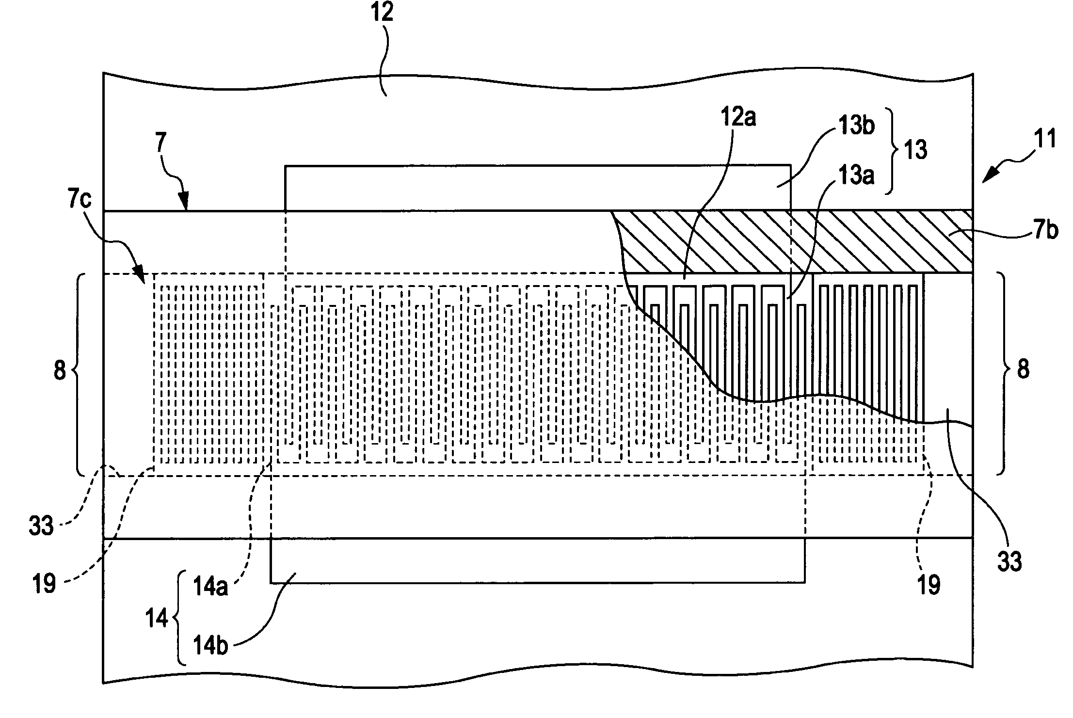
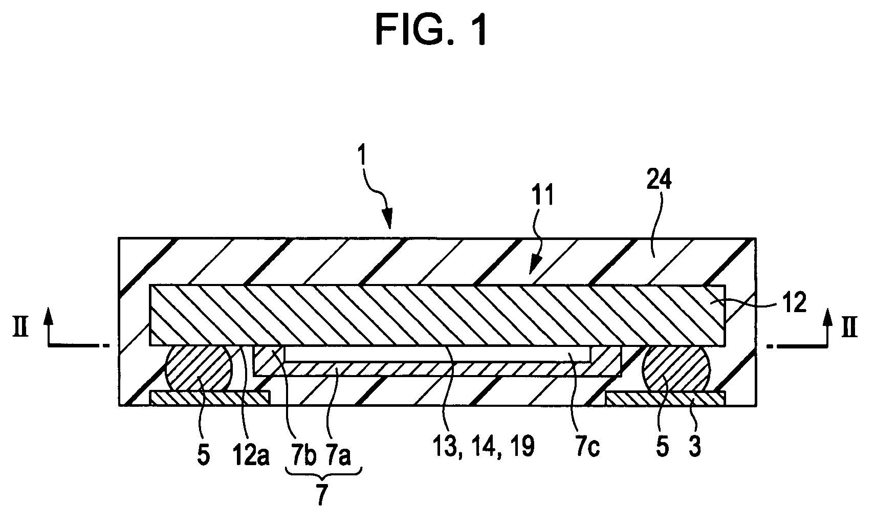
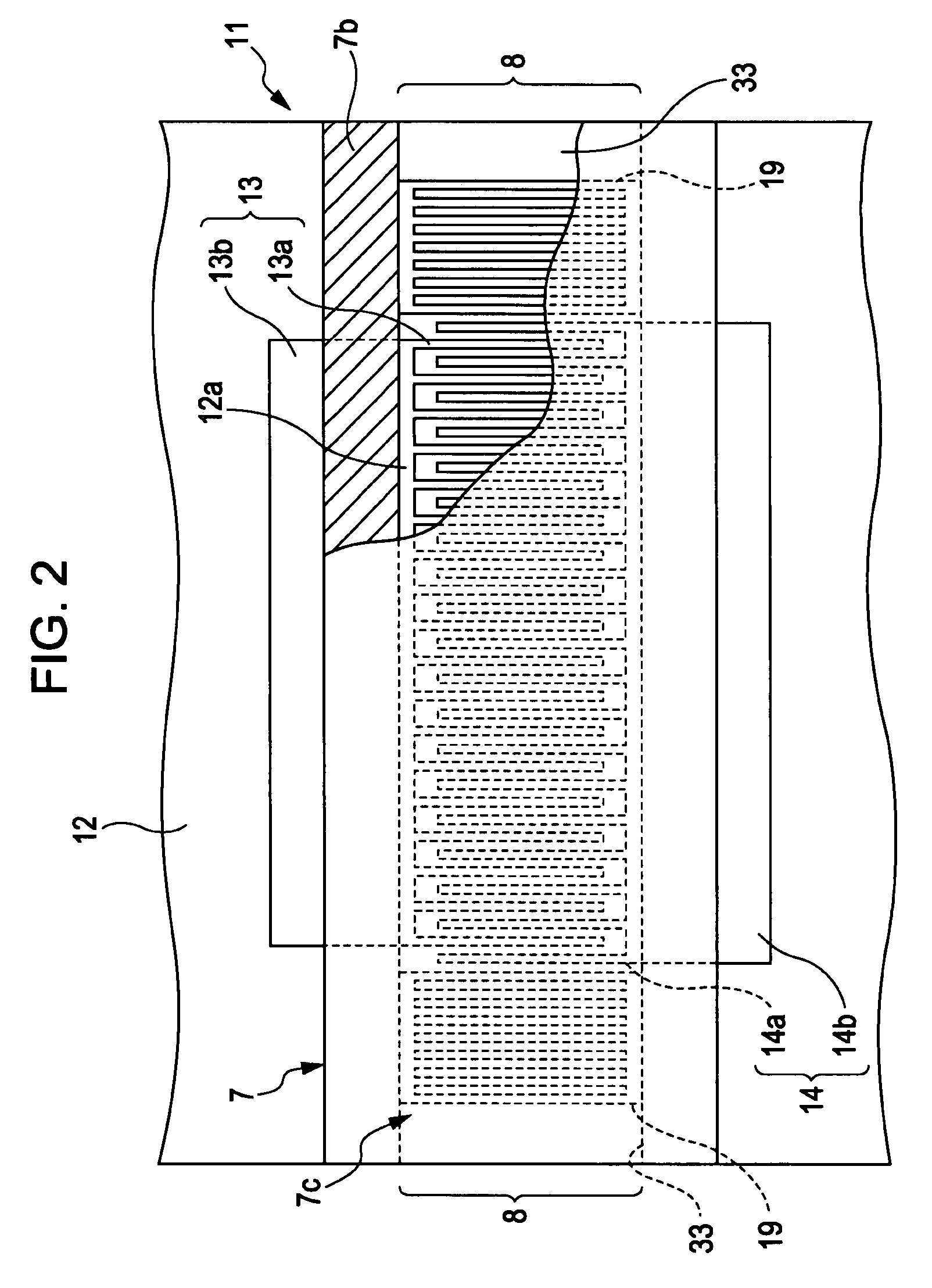
[0055]FIGS. 1 and 2 are sectional views of a structure of a surface acoustic wave device according to a first embodiment. The surface acoustic wave device shown in FIGS. 1 and 2 is an example of an electronic component that is generally called a SAW device. In each of the embodiments below, the surface acoustic wave device will be referred to as the “SAW device.” A SAW device 1 is used to function as a resonator or a band-pass filter in a communications device or an electronic device, such as a portable telephone device or a television receiver. FIG. 2 is a sectional view of the structure taken along line II-II of the SAW device 1 shown in FIG. 1. In FIG. 2, structural features not included in the cross section are added as appropriate to help one understand the description.

[0056]The SAW device 1 has a structure in which a surface acoustic wave element 11 provided with metallic bumps 5 and lead frames 3 is sealed by sealing resin 24. The sealing resin 24 is, for example, silicon oxi...

second embodiment

[0096]FIG. 13 is a sectional view of a structure of a SAW device 1a according to a second embodiment of the present invention.

[0097]The structural features and operations of the SAW device 1a according to the second embodiment are substantially the same as those of the SAW device 1 according to the first embodiment. Therefore, the same structural features and operations will not be described below, so that the description below will focus upon the differences. The structural features and operations according to the second embodiment that are the same as those according to the first embodiment will be referred to using the same reference numerals as those used in the first embodiment.

[0098]The structure of the SAW device 1a according to the second embodiment differs from that of the SAW device 1 according to the first embodiment in that it is what is called a wafer-level SAW package. In the SAW device 1a, a surface where a space-forming member 7 is not formed (that is, a surface wher...

third embodiment

[0111]FIG. 22 is a sectional view of a structure of a SAW device 1b according to a third embodiment of the present invention.

[0112]The structural features and operations of the SAW device 1b according to the third embodiment are substantially the same as those of the SAW device 1a according to the second embodiment. Therefore, the same structural features and operations will not be described below, so that the description below will focus upon the difference. The structural features and operations according to the third embodiment that are the same as those according to the first and second embodiments will be referred to using the same reference numerals as those used in the first and second embodiments.

[0113]The SAW device 1b according to the third embodiment is the same as the SAW device 1a according to the second embodiment in that it is what is called a wafer-level SAW package, but differs from the SAW device 1a in that it has a protective layer 30 deposited on a back surface 1...


PUM

PropertyMeasurementUnit
thicknessaaaaaaaaaa
shapeaaaaaaaaaa
surface acousticaaaaaaaaaa

Abstract

A method of producing a surface acoustic wave device includes a sacrificial-layer forming step of forming a sacrificial layer on a piezoelectric substrate so as to cover comb electrodes and reflectors, a space-forming-member forming step of forming a space-forming member while openings are formed near the reflectors along a surface of the sacrificial layer, a sacrificial-layer removing step of removing the sacrificial layer from the openings of the space-forming member, and a resin sealing step of sealing a surface acoustic wave element with sealing resin, the surface acoustic wave element having an excitation protection space formed between the reflectors and the comb electrodes by the space-forming member.

Description

CLAIM OF PRIORITY[0001]This application claims benefit of the Japanese Patent Application No. 2006-153776 filed on Jun. 1, 2006, which is hereby incorporated by reference.BACKGROUND OF THE INVENTION[0002]1. Field of the Invention[0003]The present invention relates to a method of producing a surface acoustic wave device including a space-forming member for forming a space between a comb electrode and a reflector on a piezoelectric substrate, and to the surface acoustic wave device.[0004]2. Description of the Related Art[0005]In recent years, in a communications component or an electronic component, such as a portable telephone or a television receiver, a surface acoustic wave device (hereunder referred to as the “SAW device”) is used as, for example, a resonator or a band-pass filter.[0006]The SAW device has a structure in which a surface acoustic wave element is covered and sealed with sealing resin. The surface acoustic wave element has, for example, a comb electrode and a reflecto...

Claims


Application Information

Patent Timeline
Patent Type & Authority Applications(United States)
IPC IPC(8): H03H9/25
CPCH03H3/08H03H9/059H03H9/1085Y10T29/49158Y10T29/49172Y10T29/49146Y10T29/42H03H9/1092H01L2924/181H01L2224/16245H01L2924/16235H01L2924/00012
Inventor OZAKI, KYOSUKE
Owner QORVO US INC
Why Eureka
Try Eureka