Integrated current sensor

Inactive Publication Date: 2007-12-06
ALLEGRO MICROSYSTEMS INC
View PDF0 Cites 108 Cited by
  • Summary
  • Abstract
  • Description
  • Claims
  • Application Information

AI Technical Summary

Benefits of technology

[0007] In accordance with one aspect of the present invention, a current sensor includes a current conductor for passing a current sensed by the current sensor. The current sensor also includes a magnetic field transducer proximate to the current conductor. The magnetic field transducer includes a sensor die with first and second opposing surfaces. The sensor die also has a

Problems solved by technology

Such devices tend to be undesirably large, both in terms of height and circuit board area.
This trapped charge tends to cause undesirable effects

Method used


Image

  • Integrated current sensor
  • Integrated current sensor
  • Integrated current sensor

Examples


Embodiment Construction

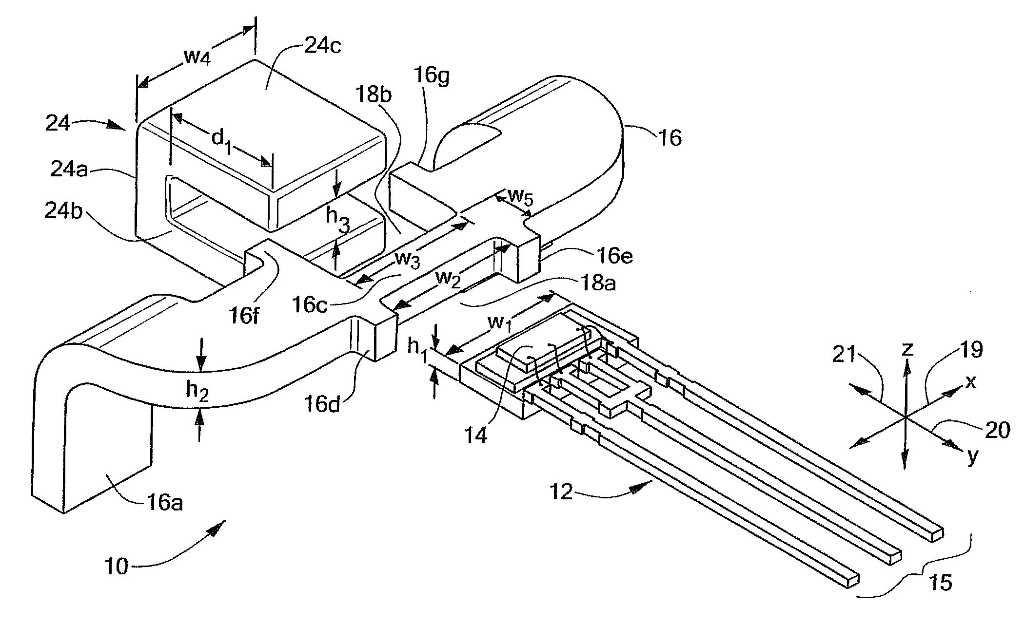
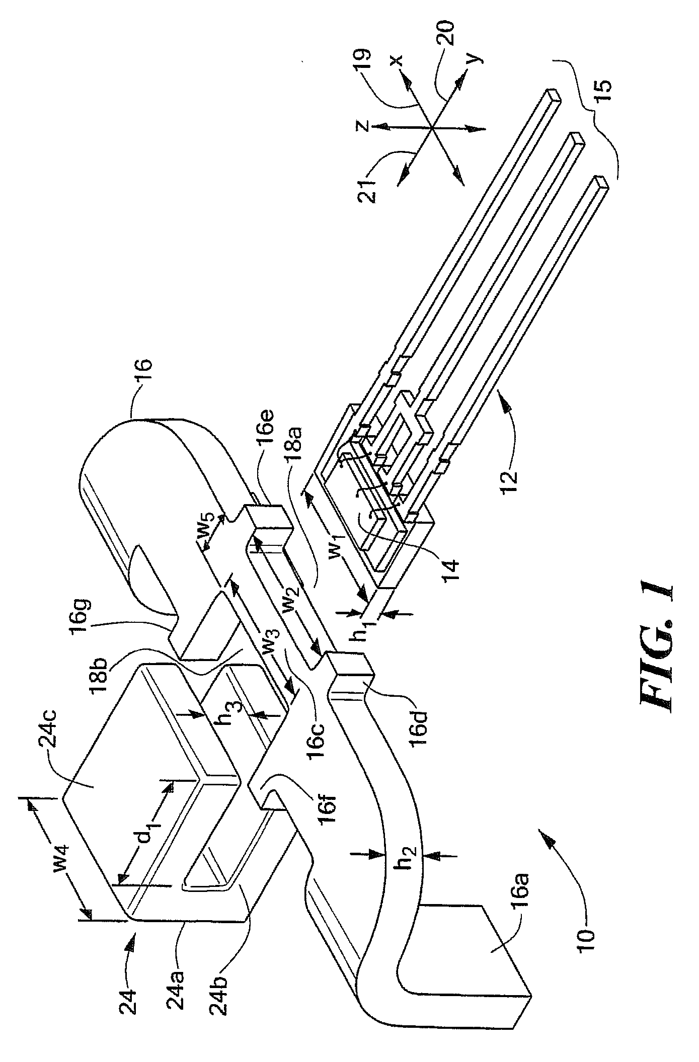
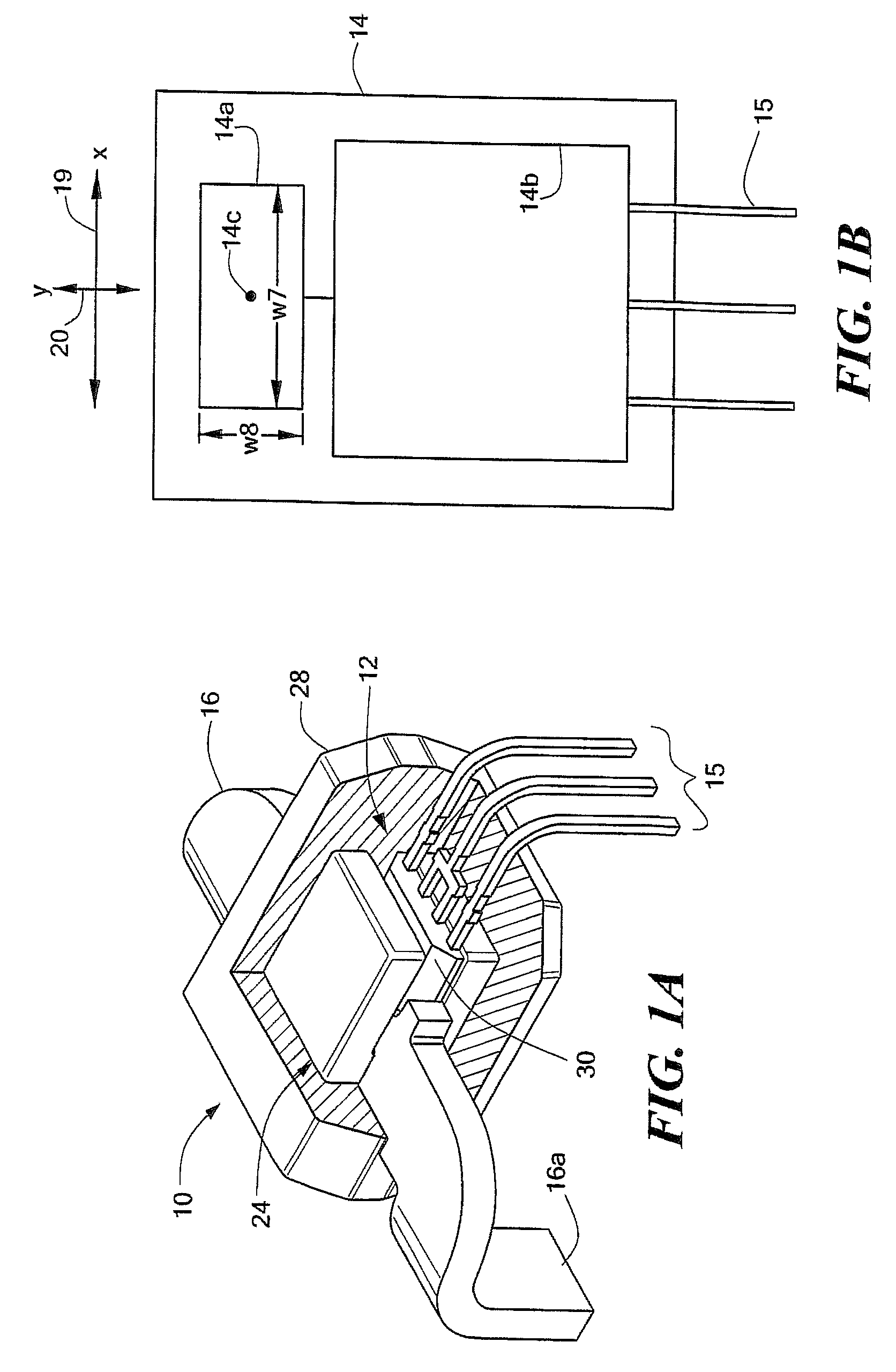
[0030] Referring to FIG. 1, a miniaturized, integrated current sensor 10 includes a magnetic field transducer, here in the form of Hall effect sensor 12, a current-carrying conductor 16 and a magnetic core 24. The conductor 16 includes features for receiving portions of the Hall effect sensor 12 and the magnetic core 24 such that the elements are maintained in a fixed position relative to each other. In the illustrated embodiment, the conductor 16 has a first notch 18a and a second notch 18b substantially aligned with the first notch. In assembly, at least a portion of the Hall effect sensor 12 is disposed in the first notch 18a. The magnetic core 24 is substantially C-shaped and has a central region 24a and a pair of substantially parallel legs 24b, 24c extending from the central region. In assembly, at least a portion of the central region 24a is disposed in the second notch 18b of the conductor such that each leg 24b, 24c covers at least a portion of a respective surface of the H...


PUM


Abstract

An integrated current sensor includes a current conductor, a magnetic field transducer, and an electromagnetic shield. The magnetic field transducer includes a sensor die. The electromagnetic shield is disposed proximate to the sensor die. The electromagnetic shield has at least one feature selected to reduce an eddy current in the electromagnetic shield.

Description

CROSS REFERENCE TO RELATED APPLICATIONS [0001] This application is a Continuation-in-Part Application of and claims the benefit of U.S. patent application Ser. No. 11 / 383,021 filed May 12, 2006.STATEMENT REGARDING FEDERALLY SPONSORED RESEARCH [0002] Not Applicable. FIELD OF THE INVENTION [0003] This invention relates generally to electrical current sensors, and more particularly to a miniaturized current sensor having an integrated conductor. BACKGROUND OF THE INVENTION [0004] As is known in the art, one type of conventional electrical current sensor uses a Hall effect magnetic field transducer in proximity to a current-carrying conductor. The Hall effect device generates an output signal having a magnitude proportional to the magnetic field induced by the current through the conductor. Typical current sensors of this type include a gapped toroid magnetic flux concentrator, with the Hall effect device positioned in the toroid gap. The Hall effect device and toroid are assembled in a...

Claims


Application Information

Patent Timeline
IPC IPC(8): G01R33/02G01R33/07G01R33/09
CPCG01R1/18G01R33/07G01R15/207H01L2224/48091H01L2224/48247H01L2924/181H01L2924/00012H01L2924/00014
Inventor TAYLOR, WILLIAM P.CUMMINGS, JOHNDOOGUE, MICHAEL C.GAGNON, JAYMANGTANI, VIJAYSHARMA, NIRMAL
Owner ALLEGRO MICROSYSTEMS INC
Why Eureka
Try Eureka