Display device and driving method thereof

a display device and driving method technology, applied in static indicating devices, instruments, optics, etc., can solve the problems of reducing the average luminance of the display device by the insertion of black, increasing the load of when light is emitted, and unable to achieve the effect of improving the quality of moving images that are displayed with luminance around the highest luminance, etc., to achieve the effect of reducing the average luminance, improving the quality of moving images, and reducing the load of when ligh

Active Publication Date: 2007-12-06
SEMICON ENERGY LAB CO LTD
View PDF10 Cites 106 Cited by
  • Summary
  • Abstract
  • Description
  • Claims
  • Application Information

AI Technical Summary

Benefits of technology

[0009]A method for realizing pseudo impulsive driving by inserting a black image, which is disclosed in References 1 and 2, is effective for improving the quality of moving images; however, there is a problem in that average luminance is lowered by the insertion of black. In addition, in order to recover the lowered average luminance to the luminance before the insertion of the black image, instantaneous luminance of a pixel needs to be high, which leads to a problem in that power consumption and a load of when light is emitted are increased.
[0010]Furthermore, in a method disclosed by the Reference 3, the effect of improving the quality of moving images is small in the case where after a bright gray scale is displayed, a bright gray scale is displayed again. In particular, the effect of improving the quality of moving images that are displayed with luminance around the highest luminance can hardly be expected. This is because, in such a case, light is continuously emitted with high luminance and the driving becomes close to the hold driving.
[0011]In view of such problems, it is an object of the present invention to provide a display device in which problems such as an increase of power consumption and increase of a load of when light is emitted are reduced by using a method for realizing pseudo impulsive driving by inserting a black image, and a driving method thereof. In addition, it is another object of the present invention to provide a display device in which an effect of improving the quality of moving images is large even when a bright gray scale is displayed, and a driving method thereof.

Problems solved by technology

A method for realizing pseudo impulsive driving by inserting a black image, which is disclosed in References 1 and 2, is effective for improving the quality of moving images; however, there is a problem in that average luminance is lowered by the insertion of black.
In addition, in order to recover the lowered average luminance to the luminance before the insertion of the black image, instantaneous luminance of a pixel needs to be high, which leads to a problem in that power consumption and a load of when light is emitted are increased.
In particular, the effect of improving the quality of moving images that are displayed with luminance around the highest luminance can hardly be expected.

Method used


Image

  • Display device and driving method thereof
  • Display device and driving method thereof
  • Display device and driving method thereof

Examples


embodiment mode 1

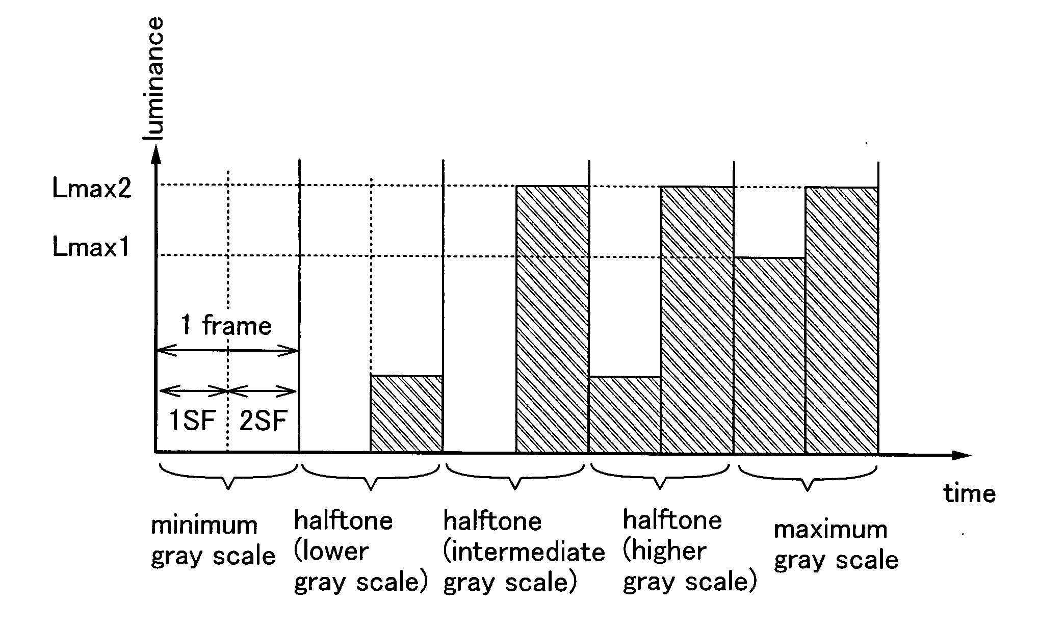
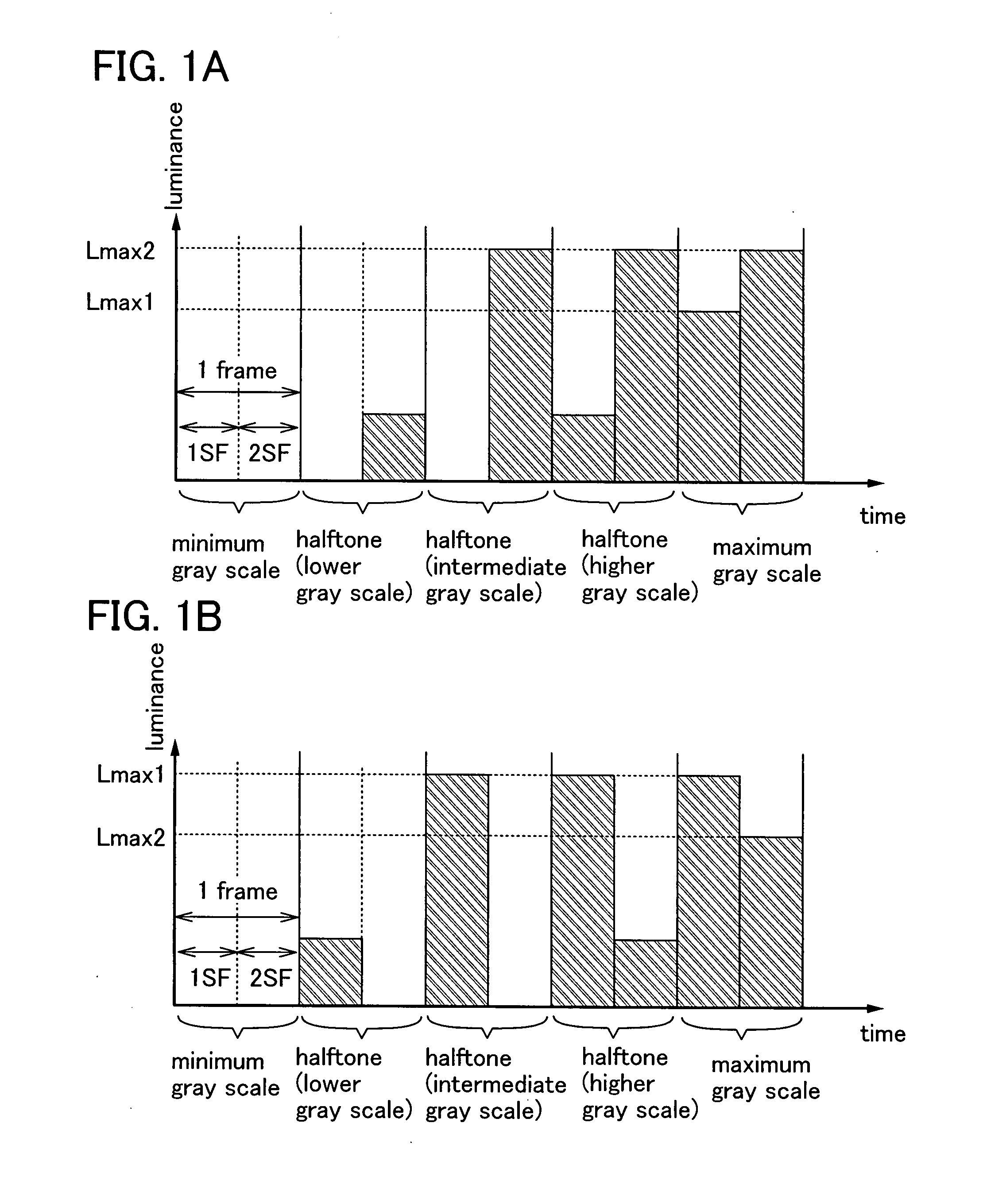
[0080]In this embodiment mode, a method for improving the quality of moving images by dividing one frame into two or more subframes and using some of the two or more subframes mainly for image display (light image) and the others mainly for reducing residual images of moving images (dark image) will be described.

[0081]Here, difference between a black image and a dark image will be described. The black image is an image where all the pixels for forming an image are in a non-lighting state or non-transmitting state, and is just an inky black image. On the other hand, the dark image is an image that is formed when a major part of pixels for forming an image is pixels which emit light with relatively low luminance. In other words, the dark image is an image where the total light emission amount of all the pixels for forming an image is smaller than the light image counterpart. In accordance with this definition, there can be a case where the black image is used as the dark image.

[0082]N...

embodiment mode 2

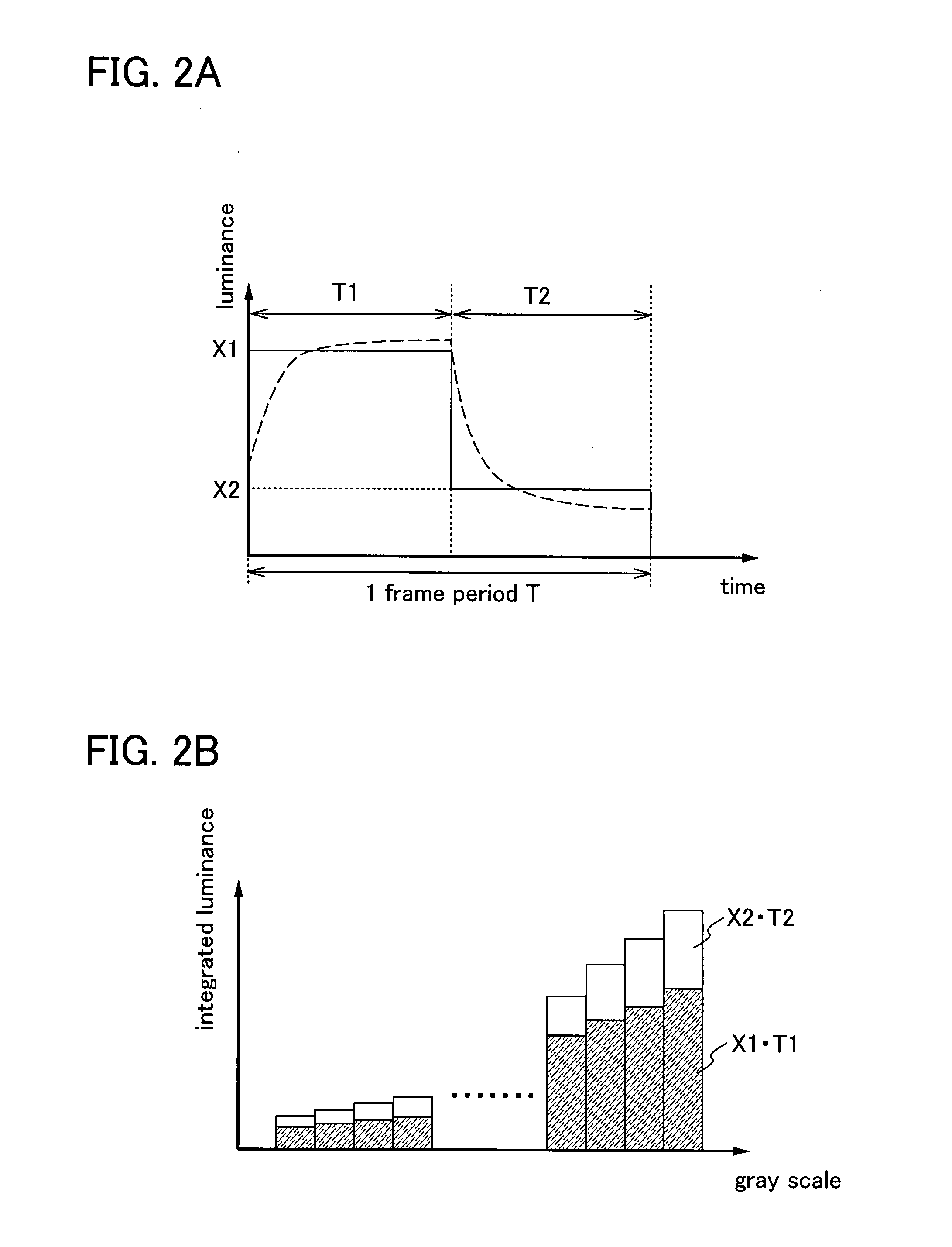
[0146]In this embodiment mode, another embodiment mode of a method in which one frame is divided into a plurality of subframes, and some of the plurality of subframes are used mainly for image display (light image) and the others are used mainly for reducing residual images of moving images (dark image), which is described in Embodiment Mode 1, will be described.

[0147]When images to be displayed are divided into light images and dark images, there are several methods different in how the luminance which is needed to express a gray scale of an image to be displayed is distributed to a plurality of subframes. In order to describe this, in this embodiment mode, a graph whose horizontal axis shows a gray scale and vertical axis shows integrated luminance, which shows a relation between integrated luminance and gray scale in 1SF, a relation between integrated luminance and gray scale in 2SF, and relation between integrated luminance and gray scale of the sum of 1SF and 2SF, will be refer...

embodiment mode 3

[0230]In this embodiment mode, a pixel structure of a display device will be described. In particular, a pixel structure of a liquid crystal display device will be described.

[0231]FIGS. 19A and 19B are a cross-sectional view and a top view, respectively, showing a pixel structure of a liquid crystal display device in which a so-called TN mode is combined with a thin film transistor (TFT). FIG. 19A is a cross-sectional view of a pixel, and FIG. 19B is a top view of the pixel. Further, the cross-sectional view of the pixel shown in FIG. 19A corresponds to a line segment a-a′ in the top view of the pixel shown in FIG. 19B. By using a liquid crystal display device having the pixel structure shown in FIGS. 19A and 19B, the liquid crystal display device can be manufactured at low costs. Furthermore, by using the liquid crystal display device having the pixel structure shown in FIGS. 19A and 19B in combination with other embodiment modes such as Embodiment Mode 1 and Embodiment Mode 2, a l...


PUM


Abstract

It is an object of the present invention to provide a display device in which problems such as an increase of power consumption and increase of a load of when light is emitted are reduced by using a method for realizing pseudo impulsive driving by inserting an dark image, and a driving method thereof. A display device which displays a gray scale by dividing one frame period into a plurality of subframe periods, where one frame period is divided into at least a first subframe period and a second subframe period; and when luminance in the first subframe period to display the maximum gray scale is Lmax1 and luminance in the second subframe period to display the maximum gray scale is Lmax2, (½) Lmax2<Lmax1<( 9 / 10) Lmax2 is satisfied in the one frame period, is provided.

Description

BACKGROUND OF THE INVENTION[0001]1. Field of the Invention[0002]The present invention relates to a device and a driving method thereof. Specifically, the present invention relates to a semiconductor device and a driving method thereof. More specifically, the present invention relates to a display device and a driving method thereof, particularly a method of improving the quality of moving images by hold driving.[0003]2. Description of the Related Art[0004]In recent years, there has been growing interests in thin display devices. As substitutes for CRT displays, liquid crystal displays, plasma displays, projection displays, and the like have been developed and becoming popular. Furthermore, field emission displays, inorganic electroluminescence displays, organic electroluminescence displays, electronic paper, and the like have been developed as next-generation display devices.[0005]In a display portion which is provided in the above-described display device, pixels each of which is a...

Claims


Application Information

Patent Timeline
Patent Type & Authority Applications(United States)
IPC IPC(8): G09G3/36
CPCG09G3/2025G09G5/10G09G3/3611G09G3/3614G09G3/3655G09G2300/0876G09G2310/024G09G2310/061G09G2320/0247G09G2320/0252G09G2320/0261G09G2320/0276G09G2320/0633G09G2330/021G09G2340/16G02F1/0121G09G3/3406G09G3/20G09G3/36G09G3/30G09G3/32G09G2320/0626
Inventor YOSHIDA, YASUNORIKIMURA, HAJIME
Owner SEMICON ENERGY LAB CO LTD
Why Eureka
Try Eureka