

Projecting device
- Summary
- Abstract
- Description
- Claims
- Application Information
AI Technical Summary
Benefits of technology
Problems solved by technology
Method used
Image

Examples
first embodiment
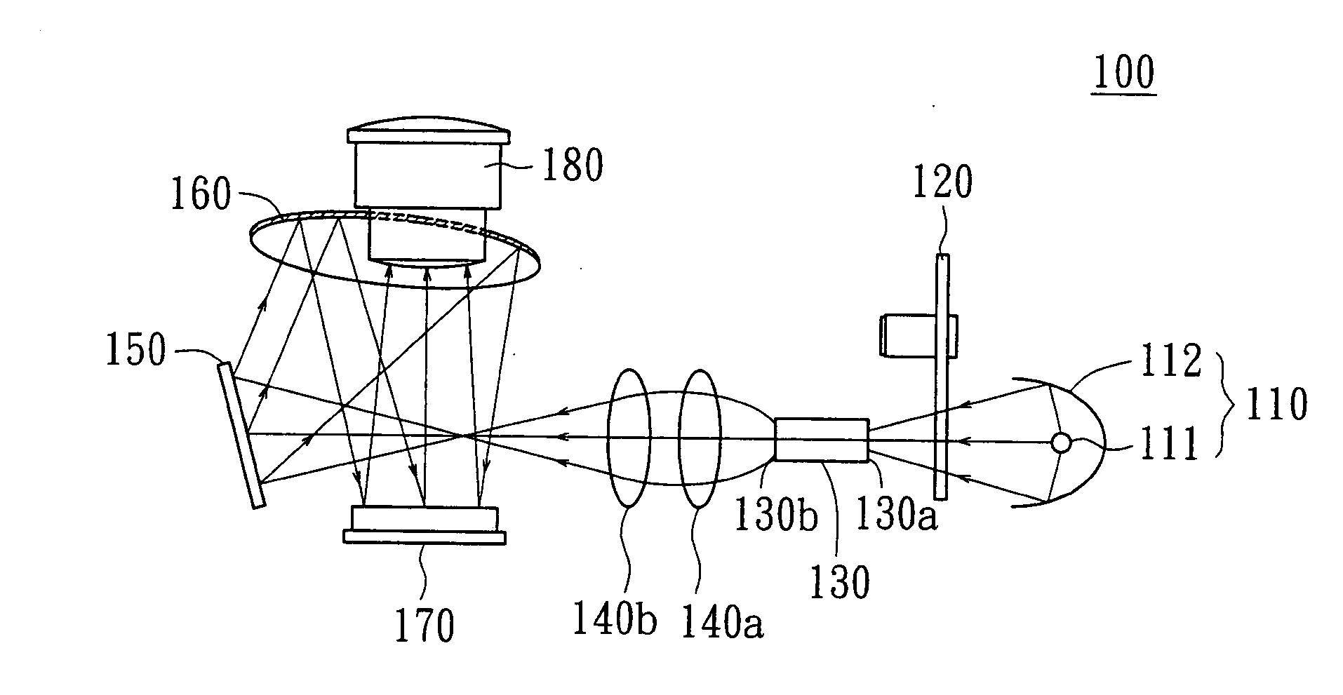
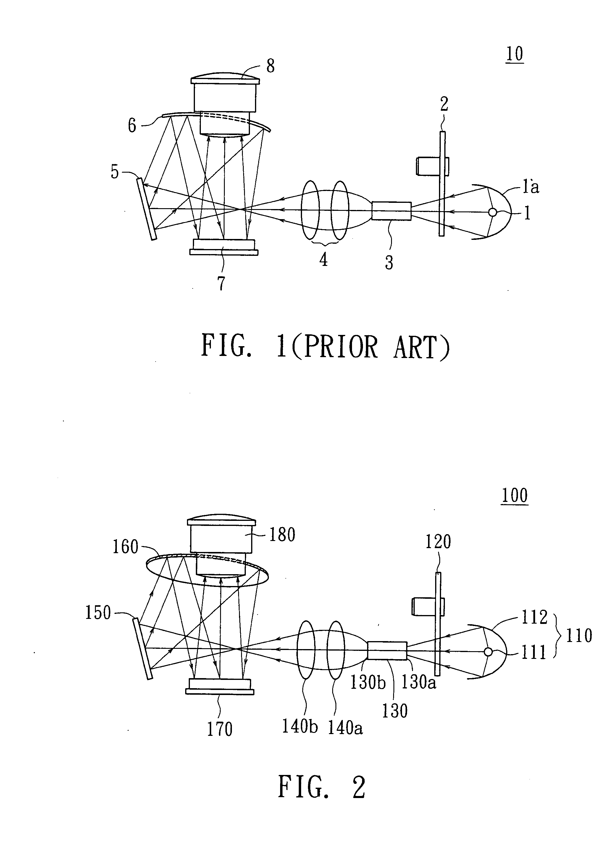
[0019]Please referring to FIG. 2, a projecting device according to a first embodiment of the present invention. For example, the projecting device is a projector or a rear projection television. The projecting device 100 of the present embodiment includes a light source 110 (such as a lamp 111 and a lamp cap 112), a color wheel 120, a light integrator 130, condenser lenses 140a and 140b, a fold mirror 150, a lens-mirror 160, a panel 170 and a projection lens 180. For example, the panel 170 is a digital micro-mirror device (DMD) chip or a liquid crystal display panel (LCD) panel.
[0020]When the projecting device 100 functions normally, the lamp 111 which electronic ballast provides with operation power generates light. The lamp cap 112 is disposed around the lamp 111 and encloses the lamp 111, for gathering the light generated by the lamp 111. The lamp cap 112 is preferably an elliptic lamp cap or a conventional parabolic lamp cap with a convex lens. The light generated by the lamp 11...
second embodiment
[0027]The projecting device of a second embodiment and that of the first embodiment are different in the structure of the lens-mirror. The rest of the components using the same reference numbers are the same and not described repeatedly.
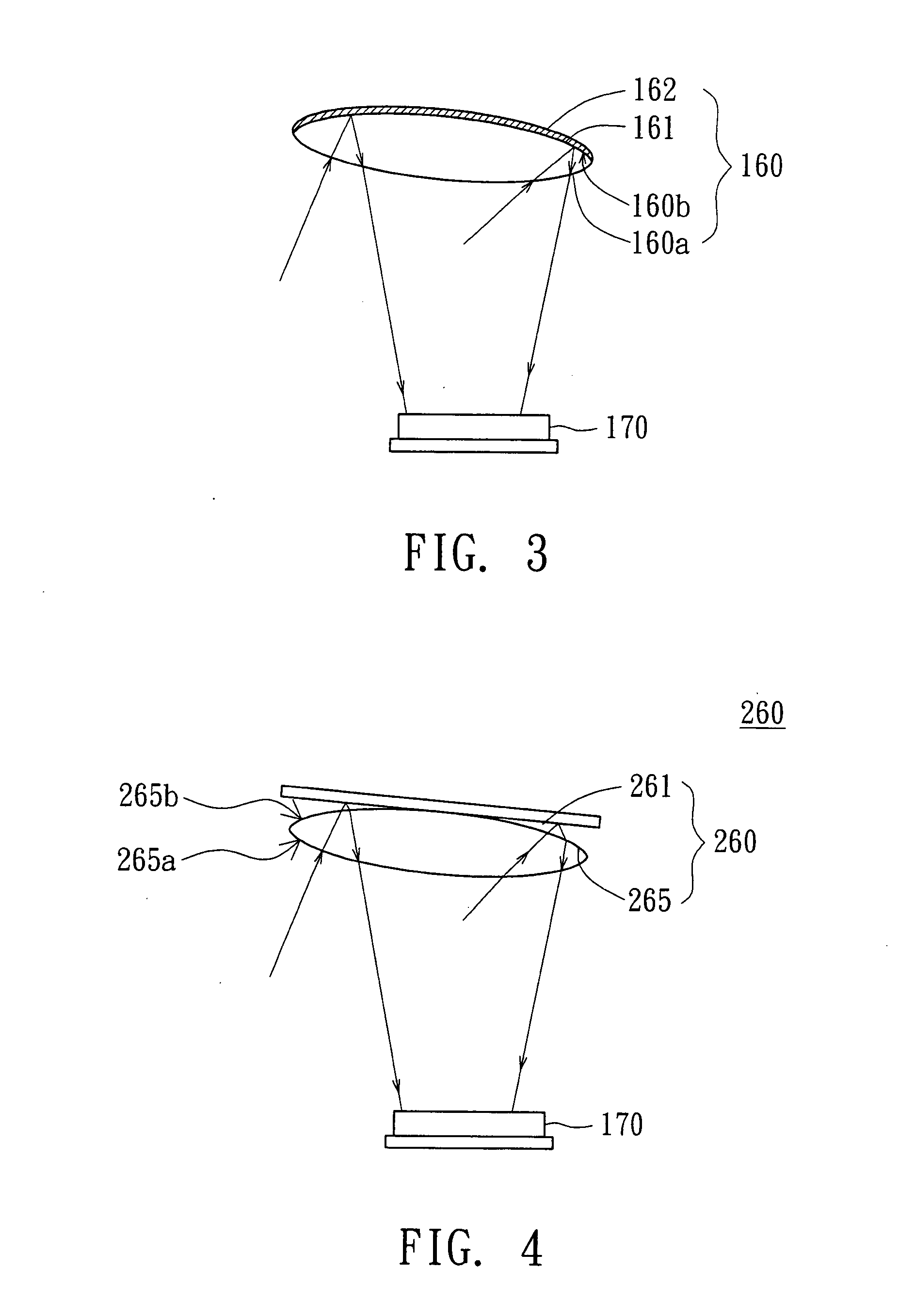
[0028]FIG. 4 is an enlarged view of the lens-mirror and the panel of the projecting device according to the second embodiment of the present invention. The lens-mirror 260 of the present embodiment includes a convex lens 265 and a reflective mirror 261. The convex lens 265 has a first convex surface 265a and a second convex surface 265b. The first convex surface 265a is positioned relatively to the light reflecting by the fold mirror 150. The reflective mirror 261 is disposed relatively to the second convex surface 265b. After passing through the first convex surface 265a (first refraction) and the second convex surface 265b (second refraction), the light is reflected (first reflection) by the reflective mirror 261 onto the second convex surface 265b...
third embodiment
[0029]The projecting device of a third embodiment and that of the first embodiment are different in the location of the lens-mirror. The location of the lens-mirror and that of the fold mirror are exchanged. The rest of the components using the same reference numbers are the same and not described repeatedly.
[0030]Please referring to FIG. 5 which illustrates the projecting device according to the third embodiment of the present invention. In the projecting device 300, the lens-mirror 350 is disposed relatively to the light source 110 for reflecting the light from the condenser lenses 140a and 140b to the fold mirror 360. The lens-mirror 350 is a convex lens with a first convex surface 350a and a second convex surface 351. The second convex surface 351 is coated with a reflective material 352 to form a reflective surface 350b. The first convex surface 350a is positioned relatively to the light. After passing through the first convex surface 350a, the light is refracted (first refract...
PUM
 Abstract
Description
Claims
Application Information