Color wheel

Inactive Publication Date: 2007-12-06
OERLIKON TRADING AG TRUEBBACH
View PDF6 Cites 3 Cited by
  • Summary
  • Abstract
  • Description
  • Claims
  • Application Information

AI Technical Summary

Benefits of technology

[0029] As the size of the outer ring further decreases when the temperature goes below zero degrees to for example −20° or even −40° it might be an advantage to provide for spacing between the segments or to assemble at −20° or even lower temperature.

Problems solved by technology

Such picture generation devices must also satisfy very high brightness requirements which can only be achieved with powerful light sources.
Broad-scale utilization in so-called low-cost display applications is only feasible if it becomes possible to produce the color wheel at very low costs despite the high quality requirements.
One disadvantage with this optical element is the fact that when inserted into the optical path, a high intensity of light has to propagate through an area which is comprised of adhesive.
Most adhesives do not withstand such intensity.
Another disadvantage of this arrangement is that the glass ring is expensive.
In addition, precise radial concentricity is difficult to achieve.
The glass ring produces additional light loss which impairs the economy of the overall arrangement.
In addition color wheel arrangements are known that feature fixing elements such as frames or spokes between the segments, but these lower the overall transmission values of the color filter rings and limit the economy.
The number and the size of these segments is very often customized, which means that for every new model of projection unit these disc shaped carriers need to be adjusted, which results in a cost wise negative change of layout.
Stress analysis showed that rigid adhesives can lead to failure due to glass cracking when storage at cold temperature is simulated.
Unfortunately this means that the inner radius of the filter segments needs to follow the outer radius of the annular disc.
Cooling down and / or heating up this assembly between −20° C. and 100° C. will therefore with a high probability result in microcracks within the glass segments.
Filter segments are typically glass segments and ring materials with CTE's equal or lower than the CTE of glass are difficult to find.

Method used


Image

  • Color wheel
  • Color wheel
  • Color wheel

Examples


first embodiment

[0046] the assembly of the color ring with the outer ring as described above is accomplished in the following manner:

[0047] A thin layer of adhesive is placed on the outer ring primary or secondary bond area or both bond areas, preferably, if given into the recess 13.

[0048] Adhesive is preferably not applied along the full rim section in order to minimize the stress in the adhesive due to different thermal expansion of segment, adhesive and outer ring. For example doted lines or discrete spots may be used.

[0049] In one embodiment these discrete spots are located at the endpoints of the outer circular arc of the segments where neighboring segments come together, because in these areas the optical active area is interrupted because of transition between two segments.

[0050] It is known that glass cracking occurs by propagation of microcracks at the edges into the glass. Therefore, according to another embodiment of the present invention, adhesive is applied to the secondary bond su...

second embodiment

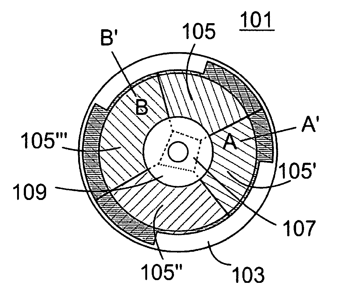
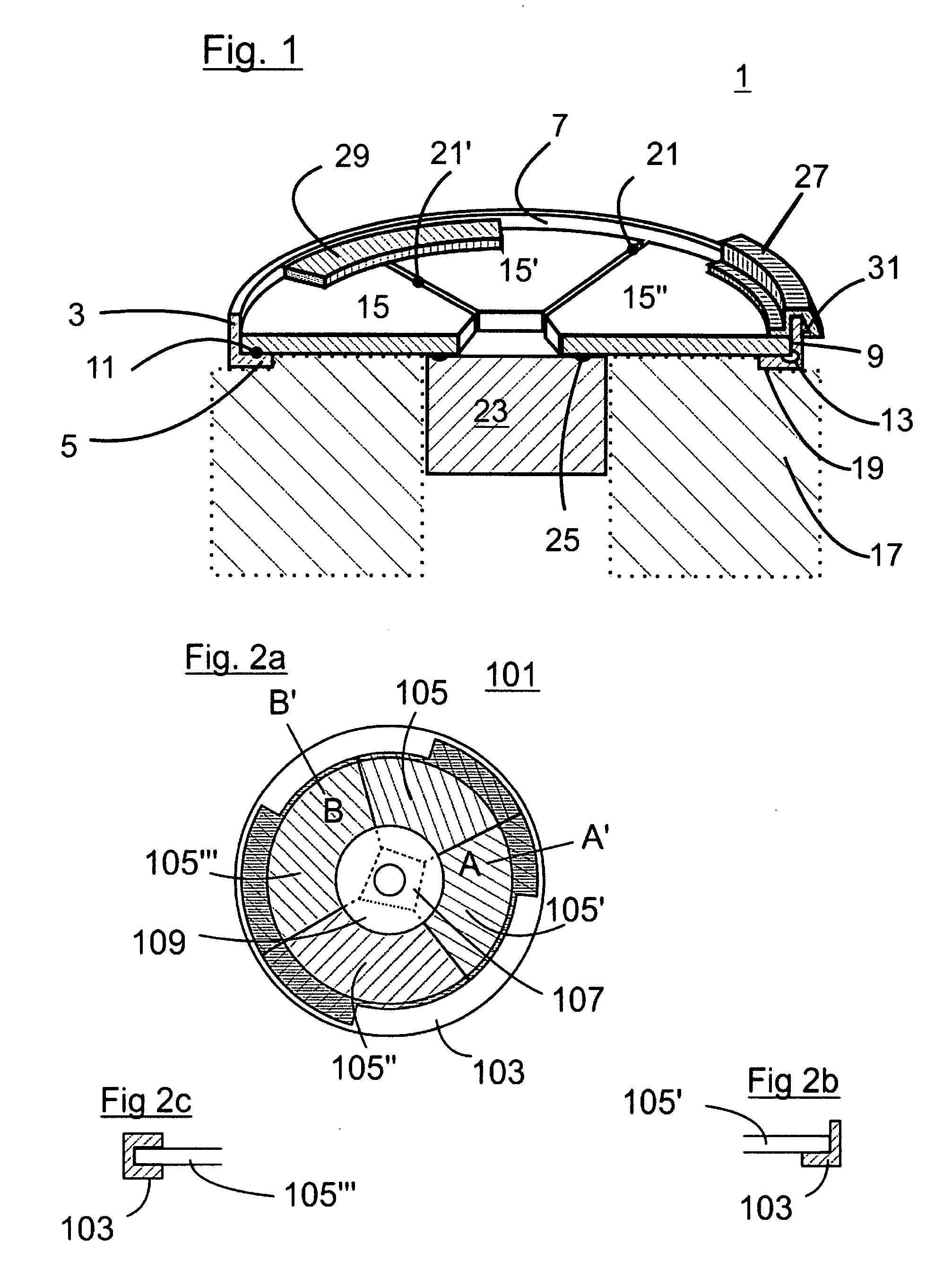
[0062]FIG. 2a shows the top view of a color wheel 101 according to the present invention. The outer ring 103 has the profile of an interrupted U-shape. In order to show this more clearly, FIG. 2b shows a cut along the line A-A′ and FIG. 2c shows a cut along the line B-B′. In this case the segments 105,105′,105″,105′″ inserted into L-shaped parts according to A-A′ and are slided into the U-shape according to B-B′. One of the L-shaped part must be at least as large as the largest of the segments 105,105′,105″,105′″. Because the segments 105,105′,105″,105′″ are assembled into the outer ring 103 before the assembly with a hub, the segments 105,105′,105″,105′″ can be slid in radially.

[0063]FIG. 2 shows in addition another possibility to realising the attachment of a hub to the segments 105,105′,105″,105′″ without glue. In this example part of the hub 107 as the form of a quadrangle. As mentioned before the “inner circle arc” of the filter segment can be modified considerably. Here the “i...


PUM


Abstract

A color wheel includes a motor and attached color ring, which includes a hub, a carrier and filter segments for being inserted into a light path. The geometry of the carrier is such that circular rings exist where the top view of the carrier fits into the area of the circular rings. The corresponding circular ring with minimum area defines outer and inner radii. The filter segments are translucent and extend radially into the circle with inner radius to contribute to a ring shaped area that is translucent to the light path as said color ring is rotated. The hub is attached to the motor and provides rotation of the color ring about an axis. At least one of the filter segments is attached to said hub. The attachment is less rigid against centrifugal forces than the fixation of the segments to the carrier so that rotation of the color ring leads to radial compressive forces exerted on all filter segments.

Description

BACKGROUND OF THE INVENTION [0001] 1. Field of the Invention [0002] The present invention relates to Color wheels used for projectors to generate color sequential illumination. [0003] 2. Description of Related Art [0004] Devices of the aforementioned type are used in applications where periodic color changes need to be produced in rapid sequence. Examples of optical systems using such devices are for example picture generation devices or display arrangements. Rear or front projection systems for television systems are typical applications. [0005] In order to produce the required rapid color changes, color filters are inserted into the optical light path in rapid sequence. For this purpose typically a disc-shaped hub is used that is equipped with circularly arranged filter segments on the periphery that form a ring. [0006] In geometry, a (circular) segment is an area of a circle informally defined as an area which is “cut off” from the rest of the circle by a secant or a chord. The c...

Claims


Application Information

Patent Timeline
IPC IPC(8): G02B5/22
CPCG02B7/006H04N9/3114G03B33/08G02B26/008G02B5/00G02B5/20
Inventor MILBOURNE, MICHAEL JOHNZUGER, OTHMAR
Owner OERLIKON TRADING AG TRUEBBACH
Why Eureka
Try Eureka