P-wave anisotropy evaluation by measuring acoustic impedance of the rock by beam-steering from within the borehole at different angles

Active Publication Date: 2007-12-06
BAKER HUGHES INC
View PDF42 Cites 33 Cited by
  • Summary
  • Abstract
  • Description
  • Claims
  • Application Information

AI Technical Summary

Problems solved by technology

This assumption was conveniently overlooked for years as the effects were relatively minor, and, given the quality of seismic data available, it was difficult to process the data using an anisotro

Method used


Image

  • P-wave anisotropy evaluation by measuring acoustic impedance of the rock by beam-steering from within the borehole at different angles
  • P-wave anisotropy evaluation by measuring acoustic impedance of the rock by beam-steering from within the borehole at different angles
  • P-wave anisotropy evaluation by measuring acoustic impedance of the rock by beam-steering from within the borehole at different angles

Examples


Embodiment Construction

[0019]The present invention is discussed with reference to specific logging instruments that may form part of a string of several logging instruments for conducting wireline logging operations. It is to be understood that the choice of the specific instruments discussed herein is not to be construed as a limitation and that the method of the present invention may also be used with other logging instruments as well.

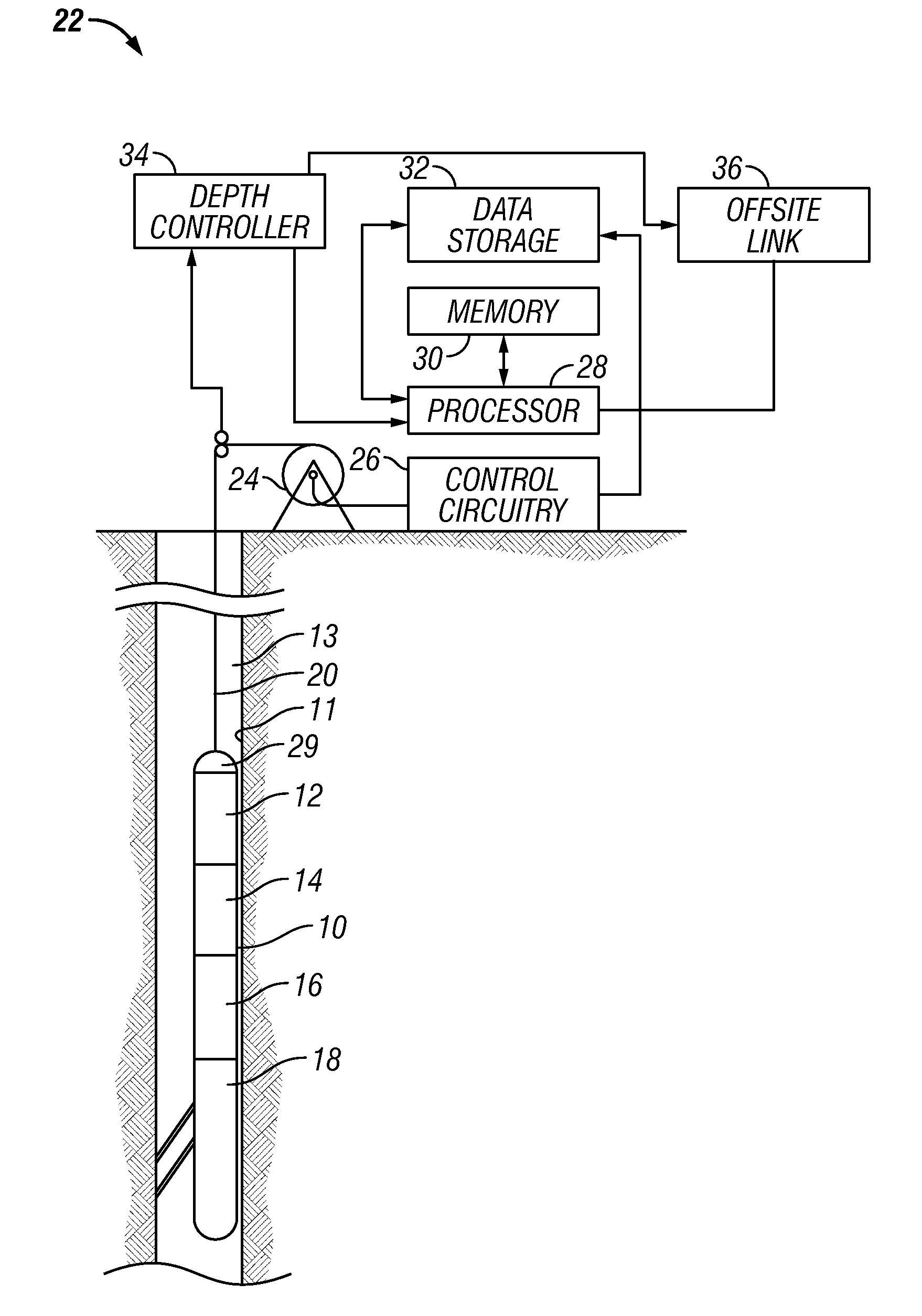
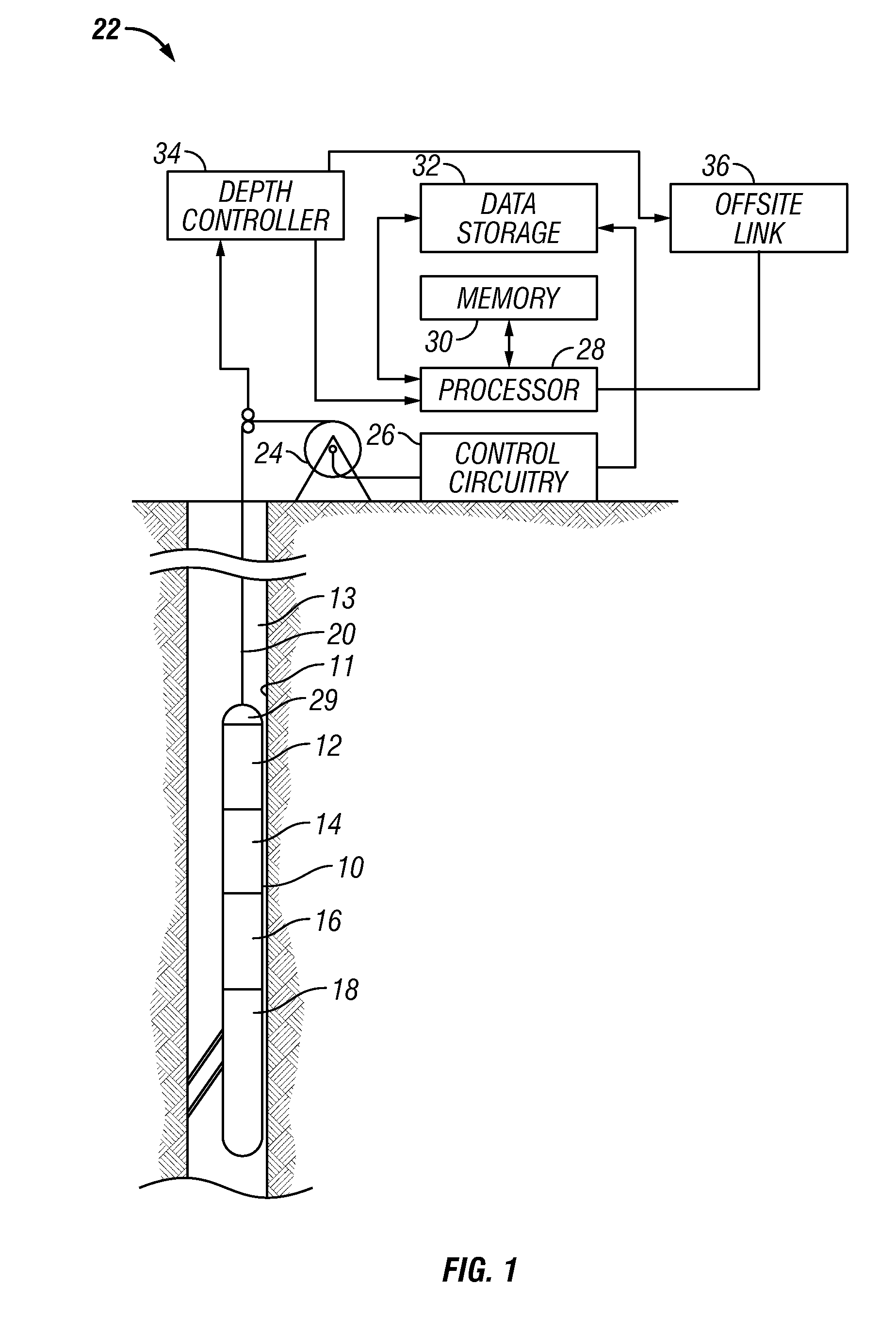
[0020]A typical configuration of the logging system is shown in FIG. 1. This is a modification of an arrangement from U.S. Pat. No. 4,953,399 to Fertl et al., having the same assignee as the present invention, the contents of which are incorporated herein by reference. Shown in FIG. 1 is a suite of logging instruments 10, disposed within a borehole 11 penetrating an earth formation 13, illustrated in vertical section, and coupled to equipment at the earth's surface, in accordance with various illustrative embodiments of the method and apparatus of the present invention. Lo...


PUM


Abstract

A phased array of transducers is used to generate elastic waves into the earth formation in a selected direction. The impedance measured at the input to the transducer array is indicative of the elastic impedance of the earth formation in the selected direction.

Description

FIELD OF THE INVENTION[0001]The present invention is a method of obtaining an anisotropic velocity model for proper depth imaging of seismic data.BACKGROUND OF THE ART[0002]The search for subsurface hydrocarbon deposits typically involves a multifaceted sequence of data acquisition, analysis, and interpretation procedures. The data acquisition phase involves use of an energy source to generate signals that propagate into the earth and reflect from various subsurface geologic structures. The reflected signals are recorded by a multitude of receivers on or near the surface of the earth, or in an overlying body of water. The received signals, which are often referred to as seismic traces, consist of amplitudes of acoustic energy that vary as a function of time, receiver position, and source position and, most importantly, vary as a function of the physical properties of the structures from which the signals reflect. The data analyst uses these traces along with a geophysical model to d...

Claims


Application Information

Patent Timeline
IPC IPC(8): G01V1/00
CPCG01V1/50G01V1/44G01V1/46
Inventor DUBINSKY, VLADIMIRTANG, XIAO MINGZHENG, YIBINGPATTERSON, DOUGLAS J.
Owner BAKER HUGHES INC
Why Eureka
Try Eureka