Fully Saturated Multi-Tone Transceiver

a transceiver and fully saturated technology, applied in the field of wireless communications, can solve the problems of linear amplification using less efficient amplifiers, significant increases in throughput and range at a similar bandwidth and power expenditure, and consuming more power

Inactive Publication Date: 2007-12-06
COBHAM ADVANCED ELECTRONICS SOLUTIONS
View PDF19 Cites 9 Cited by
  • Summary
  • Abstract
  • Description
  • Claims
  • Application Information

AI Technical Summary

Benefits of technology

[0007] One aspect of the invention is a method of transmitting a multi-tone signal decomposed into a plurality of constant envelope signals over a multiple input multiple output (MIMO) system. In this embodiment, the MIMO system has two or more transmitting antennas, and the method comprises: (a) generating first and second signals having different frequencies; (b) transmitting the first signal on a first antenna and the second signal on a second antenna for a predetermined time period; and (c) transmitting the second signal on the first antenna and the first signal on the second antenna for the predetermined time period. Preferably, the signals are transmitted using an amplifier that is essentially fully saturated.

Problems solved by technology

MIMO allows for multiple antennas to broadcast messages simultaneously, resulting in significant increases in throughput and range at a similar bandwidth and power expenditure as single-input single-output systems (SISO).
However, this spatial diversity comes at a price.
These signals require linear amplification which utilizes less efficient amplifiers that consumes more power, generate more heat and are more expensive than other amplifier counterparts used in constant envelope signaling.
Additionally, by using non-constant envelope signaling, standard MIMO techniques do not address frequency diversity power efficiently.

Method used


Image

  • Fully Saturated Multi-Tone Transceiver
  • Fully Saturated Multi-Tone Transceiver
  • Fully Saturated Multi-Tone Transceiver

Examples


Embodiment Construction

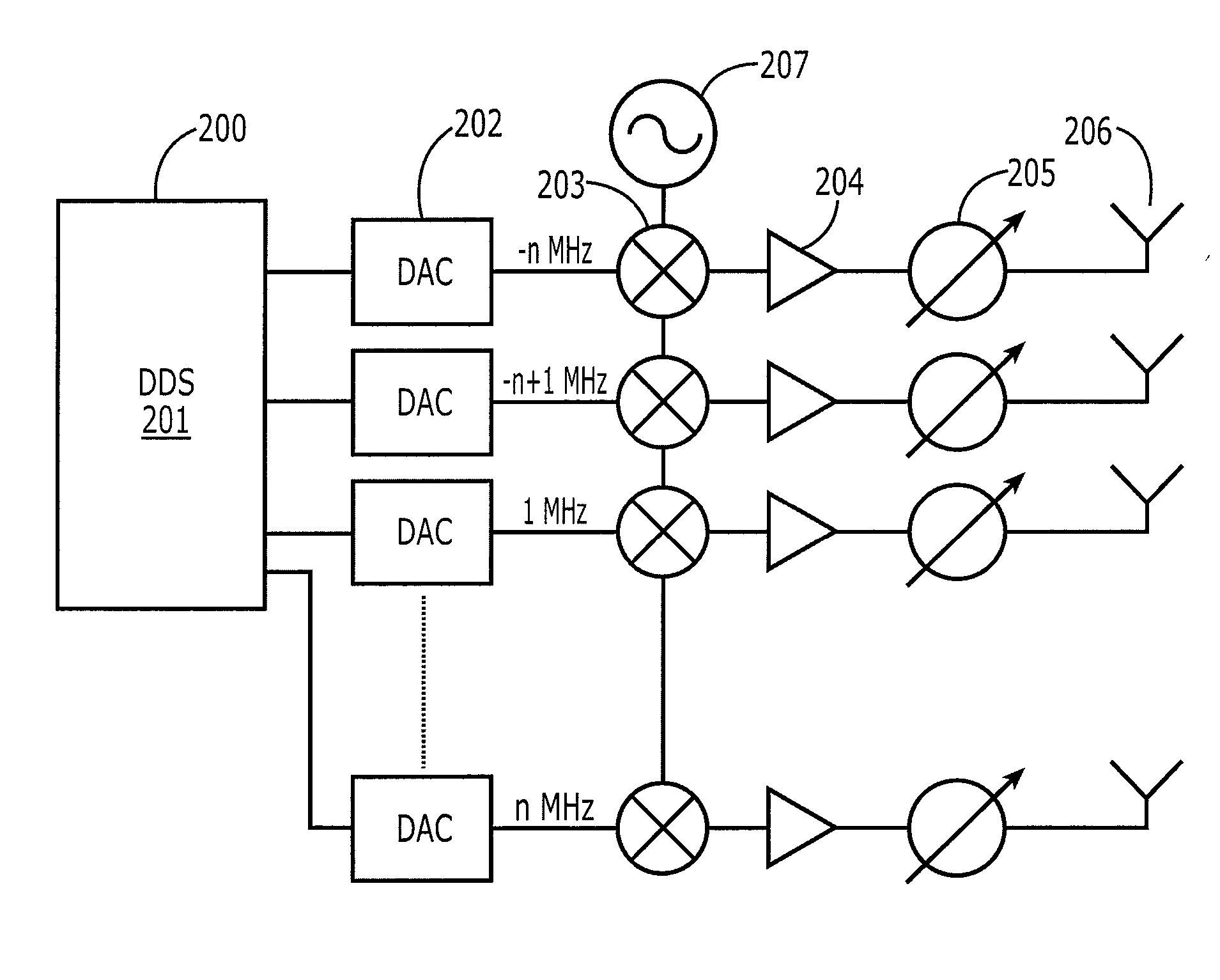
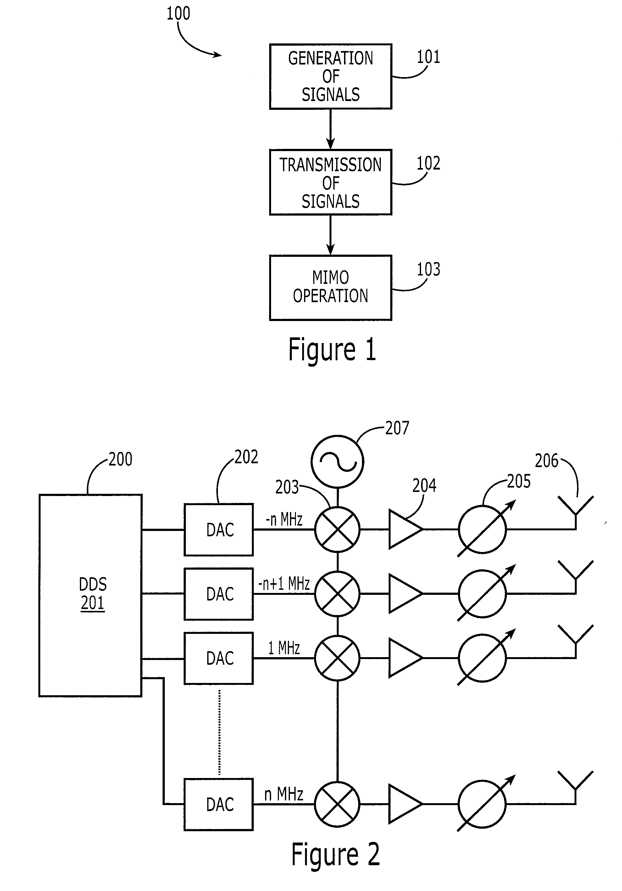
[0013] The present invention provides a method and system for transmitting a multi-frequency signal composed of discrete tones of constant envelope parts that are amplified by a bank of fully saturated transmitters operating in their most power efficient mode. After amplification and transmission, the signals are multiplexed in the air as opposed to multiplexing before amplification, which allows for more efficient amplification as well. This concept is related to U.S. Pat. No. 7,151,476, hereby incorporated by reference. Therefore, the present invention provides a wireless transmitter that operates at high efficiency while transmitting a multi-tone signal.

[0014] As digital processing technology advances, the present invention will be more and more advantageous since both processing speed and power efficiency can still be improved, but are currently being held back by hardware technology. Furthermore, power efficiency of linear amplification, as is used in prior art MIMO techniques...


PUM


Abstract

The present invention provides a method and system for transmitting a multi-frequency signal composed of discrete tones of constant envelope parts that are amplified by a bank of fully saturated transmitters operating in their most power efficient mode. After amplification and transmission, the signals are multiplexed in the air as opposed to multiplexing before amplification that allows for more efficient amplification as well. In a preferred embodiment, the system has two or more transmitting antennas, and the method comprises: (a) generating a first signal of a first carrier frequency and a second signal of a second carrier frequency; (b) transmitting the first signal of a first carrier frequency on a first antenna and the first signal of a second carrier signal on a second antenna for a predetermined time period; and (c) transmitting a second signal of the second carrier frequency on said first antenna and a second signal of the first carrier frequency on the second antenna for the predetermined time period. Preferably, the signals are transmitted using an amplifier that is essentially fully saturated.

Description

FIELD OF THE INVENTION [0001] The present invention is directed towards wireless communications, more specifically to multi-tone wireless communications. BACKGROUND OF THE INVENTION [0002] This application claims priority to U.S. Provisional Application No. 60 / 809,901, filed May 31, 2006, which is hereby fully incorporated by reference. [0003] In recent years, one important area of research and development in wireless communications has been multiple-input multiple-output (MIMO) development. MIMO allows for multiple antennas to broadcast messages simultaneously, resulting in significant increases in throughput and range at a similar bandwidth and power expenditure as single-input single-output systems (SISO). [0004] One concern with wireless communications is spatial diversity. Spatial diversity results when a message is obstructed by some external phenomena. For example, a mountain may be blocking a wireless transmission. In general, MIMO technology increases the spatial diversity ...

Claims


Application Information

Patent Timeline
Patent Type & Authority Applications(United States)
IPC IPC(8): H04L1/02H04L27/00
CPCH04L27/2637
Inventor EGRI, ROBERTPERRAUD, LAURENT
Owner COBHAM ADVANCED ELECTRONICS SOLUTIONS
Why Eureka
Try Eureka