Chilled finish roller system and method

a technology of chilling finish and roller, applied in the field of chilling finish roller system and method, can solve the problems of large differences in toner gloss, poor quality, and inability to produce various limitations of non-contact fusing image quality, etc., and achieve the effects of improving the quality of print finish, sharp increase of the modulus of elasticity, and improving color density

Inactive Publication Date: 2007-12-06
EASTMAN KODAK CO
View PDF32 Cites 27 Cited by
  • Summary
  • Abstract
  • Description
  • Claims
  • Application Information

AI Technical Summary

Benefits of technology

[0005]In accordance with an object of the invention, both an apparatus and a method are provided for improving the quality of print finishes using a non-contact fuser of toner on the substrate, in conjunction with cooling finish rollers located subsequent the fuser, such that the toner deposited on the substrate exhibits a sharp increase of the modulus of elasticity when it contacts the cooler rollers. The cooler rollers also provide pressure to assist image dot spreading for increased color density in low color density areas, and to cast the roller surface texture onto the toner surface to modulate the gloss to the desired levels, and to cool crystalline sites at a specific rate to also modulate the gloss levels.

Problems solved by technology

This is due to the fact that the surface finish of the roller coating is normally used to act as a gloss modulator in contact fusing systems but is not available in the non-contact fusing systems currently available.
Without the use of the roller, the non-contact fuser can cause large differences in toner gloss (luster) from light scattering off of separate toner particles at low to mid range color densities that produce low gloss, and solid high density layers of toner that produce high gloss.
Non-contact systems toner formulations can also produce various limitations for non-contact fusing image quality.
These toner types tend to have other associated problems such as cratering which leads to poor quality results.
In some cases the non-wetting of the toner melt can lead to image artifacts such as lower gloss and image density in a manner similar to cratering.

Method used


Image

  • Chilled finish roller system and method
  • Chilled finish roller system and method
  • Chilled finish roller system and method

Examples


Embodiment Construction

[0019]The present description will be directed in particular to elements forming part of, or cooperating more directly with, apparatus and methods in accordance with the present invention. It is to be understood that elements not specifically shown or described may take various forms well known to those skilled in the art.

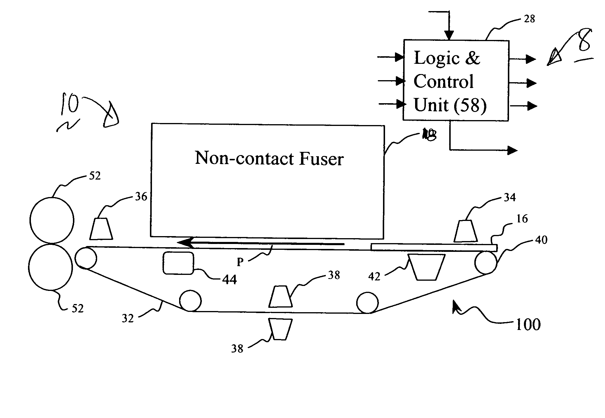
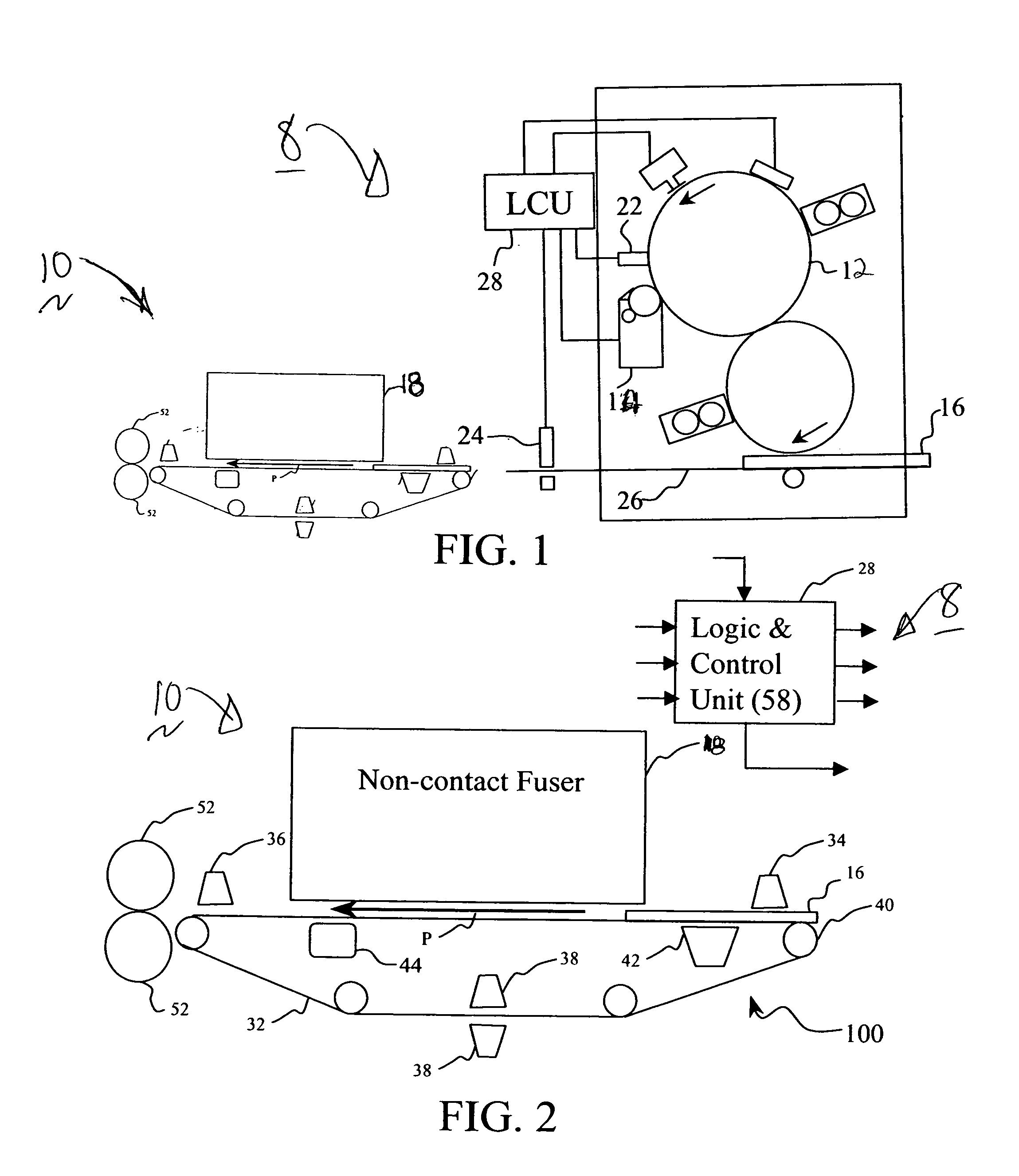
[0020]FIG. 1, shows generally, schematically, a portion of an electrographic apparatus 8 with a chilled finish roller system 10, generally referred to as an electrographic printer which incorporates a printing system in accordance with the methods and systems described below.

[0021]The electrographic printer 8 includes a moving electrographic imaging member such as a photoconductive drum 12, which is driven by a motor to advance the drum, which advances the receiver 16 in the direction indicated by arrow P. Alternatively, drum 12 may be a belt that is wrapped around a drum or it may be a belt that is wrapped around one or more rollers.

[0022]The electrographic appara...


PUM


Abstract

An apparatus for fixing of toner onto a receiver, including: a non-contact fuser capable of fusing one or more layers of toner on a receiver such that one or more toner layers reach a fusing temperature above a glass transition temperature. The apparatus also includes one or more cooling finish rollers located downstream from the non-contact fuser to lower the toner temperature.

Description

FIELD OF THE INVENTION[0001]The invention relates generally to the field of print finishing, and more particularly to a device and method for fixing toner onto a substrate, also referred to as a receiver, using chilled finish rollers.BACKGROUND OF THE INVENTION[0002]Many electrographic printers / copiers use rollers to feed material to a nip near a web. A pressure sensitive roller and a heated roller form a nip. During fusing, after printing, the pressure sensitive roller and heated roller are in pressure contact with one another in what is referred to as contact fusing. If heated rollers do not contact the substrate it is referred to as non-contact fusing.[0003]In electrographic printers many of the non-contact fusing systems have suffered from the absence of a contact roller for toner dot spreading, which acts as an assist for toner / substrate surface wetting and gloss modulation. This is due to the fact that the surface finish of the roller coating is normally used to act as a gloss...

Claims


Application Information

Patent Timeline
Patent Type & Authority Applications(United States)
IPC IPC(8): G03G15/20
CPCG03G9/0821G03G9/08782G03G9/08795G03G9/08797G03G2215/00805G03G15/6573G03G2215/0081G03G15/2021G03G15/2007G03G15/20G03G15/2098
Inventor CIASCHI, ANDREWTYAGI, DINESHHURST, JAMES H.CHOWDRY, ARUNSTELTER, ERIC C.BOBO, ROBERT D.ASLAM, MUHAMMED
Owner EASTMAN KODAK CO
Why Eureka
Try Eureka