
Powered paint brush

Inactive Publication Date: 2007-12-06
CASTELLANA JERRY D
View PDF23 Cites 16 Cited by
  • Summary
  • Abstract
  • Description
  • Claims
  • Application Information

AI Technical Summary

Benefits of technology

[0007]The present invention provides a pump fed paint brush which has a paint distribution which delivers paint to the proper portion of the bristles and does not unduly inhibit the proper flexure of the bristles when painting with strokes in a direction perpendicular to the wide dimension of the bristles (primary stroke) or in a direction parallel to the wide dimension of the bristles (edge stroke). In addition, the present invention provides a pump fed paint brush in which the entire device is contained in the hand-held paint brush such that there are no tubes between a remote reservoir and the paint brush.

Problems solved by technology

However, these alternative painting devices still do not have the control of a paint brush, nor do they provide the distinct and often desirable finish of paint brush.
However, these previously known power-fed paint brushes have a number of drawbacks.
For one, the tube connecting the paint brush to the paint reservoir can be a nuisance because it gets in the way of the painting motion and makes it harder to perform the typical back and forth painting strokes.
In addition, the paint distribution devices are ineffective for various reasons.
This creates problems with dripping and the flow of the paint to the lower end of the bristles and application to a surface being coated.
And for those distribution devices which do extend to near the lower end of the bristles, the devices tend to inhibit the proper flexure of the bristles during painting.
Although the inserts are disclosed as being flexible, it can be seen that such a device is very stiff in the transverse direction (i.e. the insets flex along with the bristles when bent by using the wide plane of the brush, but is very stiff when bent by using the narrow edge of the brush).

Method used


Image

  • Powered paint brush
  • Powered paint brush
  • Powered paint brush

Examples


Embodiment Construction

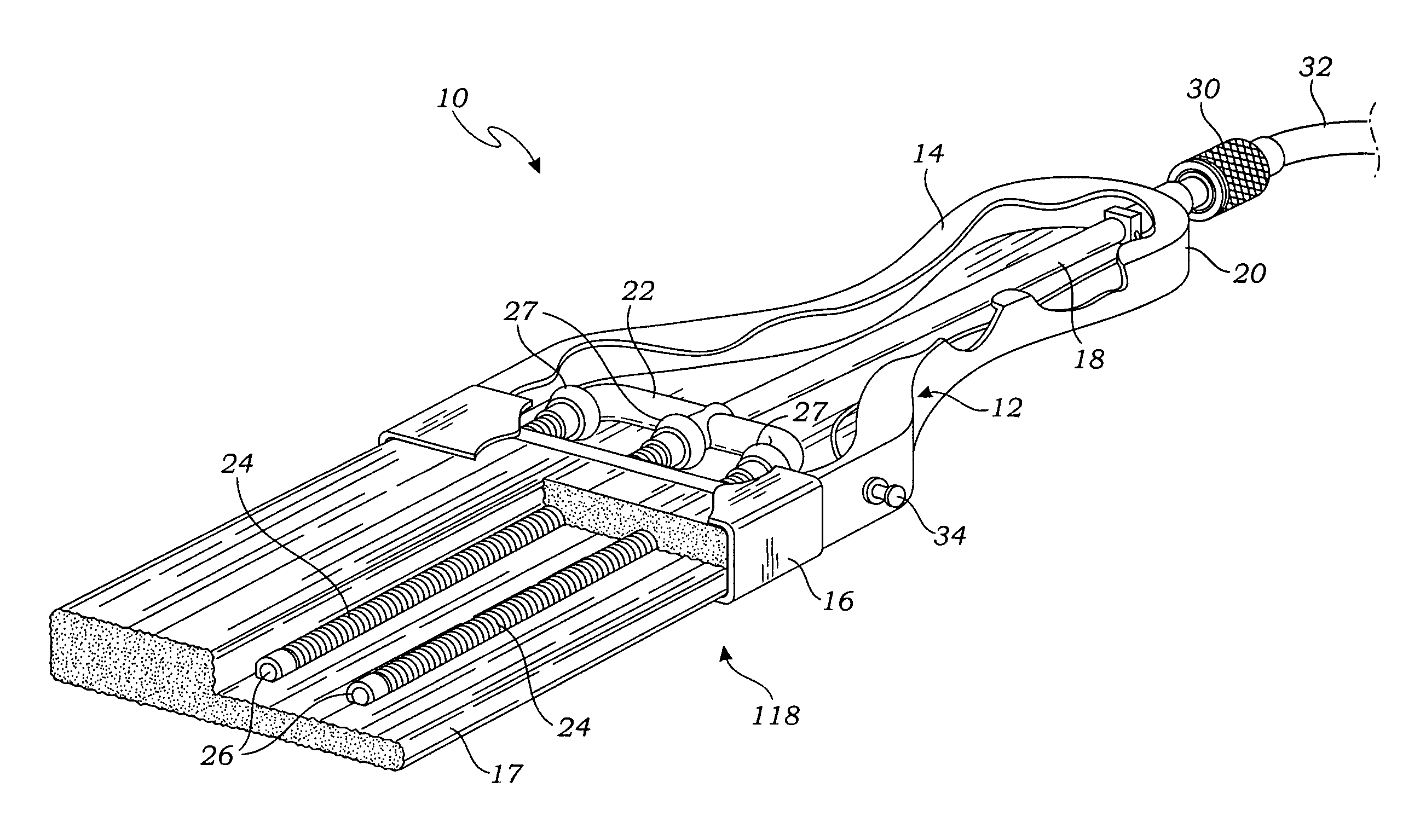
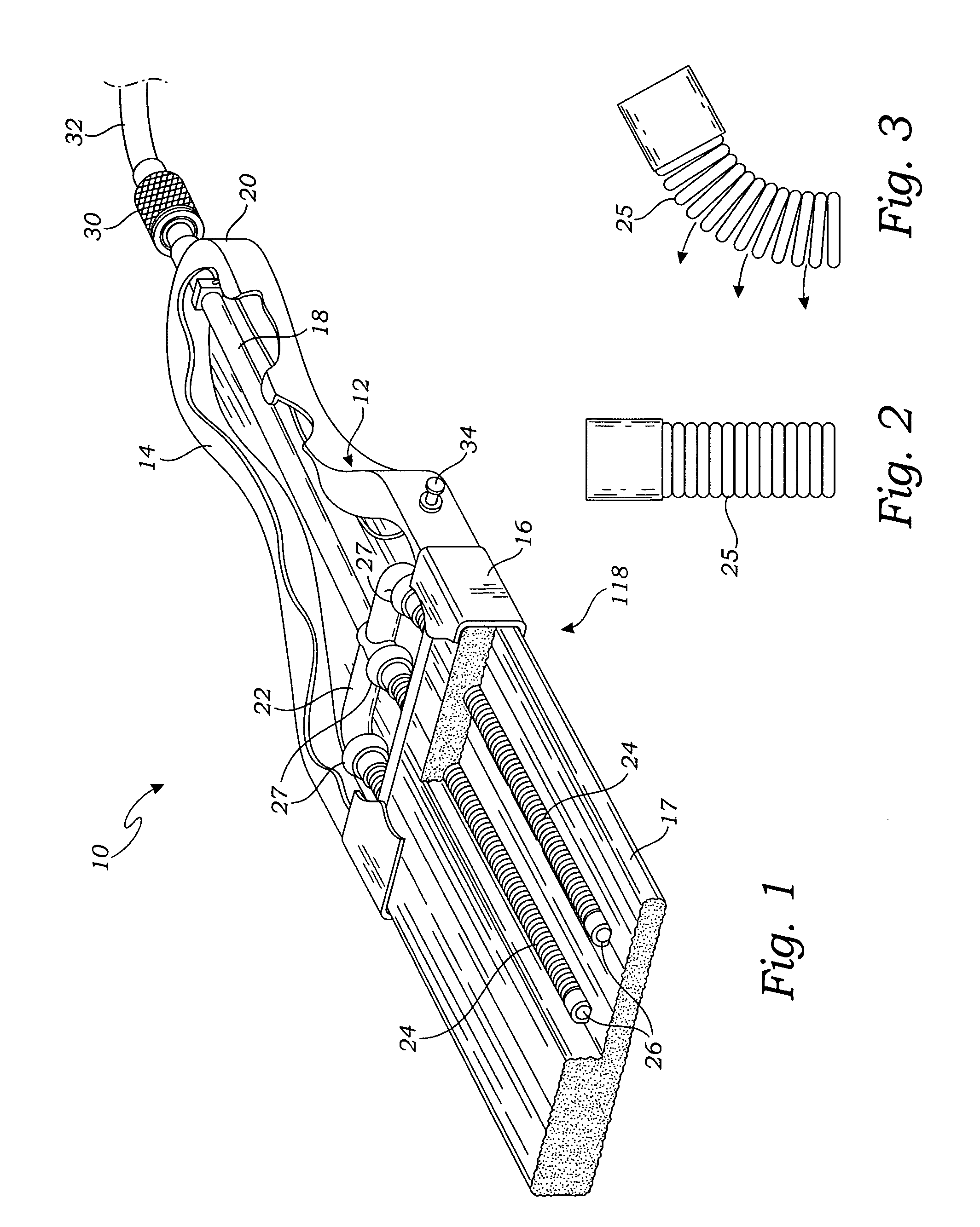
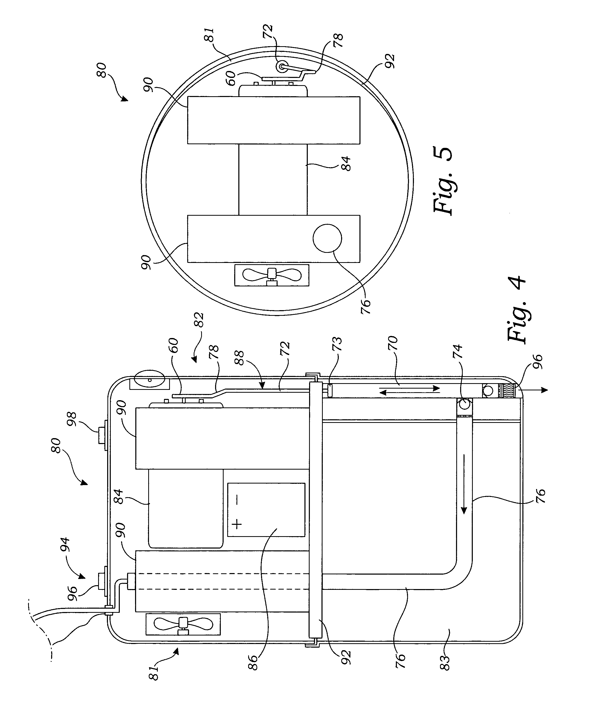
[0020]Turning to FIG. 1, a power fed paint brush 10 according to the present invention is shown. The power fed paint brush 10 comprises a main body 12 having a handle 14 and a bristle stock 16. A bristle bundle 17 is retained by the bristle stock 16. The main body 12 may be formed of any suitable material such as wood, plastic or metal.

[0021]A fluid flow path 18 in the form of a bore or a tube within the bore runs from the proximal end 20 of the handle to a manifold 22 located in main body 12 near the bristle stock 16. The manifold 22 has a single inlet from the flow path 18 and multiple outlets in fluid connection with a plurality of fluid distribution members 24. The manifold 22 may be as simple as a junction of fluid flow paths such as the intersection of several tubes, or it may be a block having one inlet and a plurality of outlets.

[0022]The fluid distribution members extend into the bristle bundle 17 and extend to a point near the distal end of the bristles. The fluid distribu...


PUM


Abstract

A powered-pump fed paint brush comprises a brush assembly and a pump unit. The brush assembly includes a main body having a handle and a brush stock and a bristle bundle secured in the brush stock. A plurality of fluid distribution members extend into the bristle assembly and are multidirectionally flexible such that the distribution members flex substantially freely with the flex of the bristles in any direction. The fluid distribution members each have a proximal end which is in fluid communication with a source of pressurized fluid from the pump unit and an open distal end within the bristle bundle which applies the fluid to the bristles. A fluid supply pathway extends through the main body from fluid distribution members to the outlet of the pump unit. The pump unit comprises a pump, a motor and battery for powering the pump, and a fluid reservoir. The pump has a pump inlet in fluid communication with a fluid reservoir and a pump outlet in fluid communication with the fluid supply pathway. The pump unit may be separate from the brush assembly and connected thereto by a supply tube or it may be entirely disposed on the main body of the paint brush resulting in a completely self-contained powered paint brush system.

Description

FIELD OF THE INVENTION[0001]The present invention relates generally to paint brushes and more particularly to paint brushes having powered paint supply to the paint brush.BACKGROUND OF INVENTION[0002]Paint brushes have been around for a very long time and are known to be relatively effective devices for applying a paint, varnish or other coating to a surface being coated. Throughout this specification, the term paint shall refer to any coating which may be applied to a surface with a paint brush, including without limitation, paint, varnish, stain, lacquer, polish, glaze, finish or other coating which can be applied with a paint brush.[0003]Generally, a paint brush has a bundle of bristles having one end secured in a stock or head which has a handle. With a conventional paint brush, the bristles are dipped in a container of paint, such as a bucket, tray of cup. It order to most effectively apply the paint with the paint brush, it is important to get the right amount of paint on the ...

Claims


Application Information

Patent Timeline
IPC IPC(8): A46B11/06A46B11/04
CPCA46B11/063A46B2200/202A46B11/066
Inventor CASTELLANA, JERRY D.
Owner CASTELLANA JERRY D
Features
  • Generate Ideas
  • Intellectual Property
  • Life Sciences
  • Materials
  • Tech Scout
  • Unparalleled Data Quality
  • Higher Quality Content
  • 60% Fewer Hallucinations
Learn More