Rotary Compressor

a compressor and rotary technology, applied in the direction of positive displacement liquid engine, piston pump, liquid fuel engine, etc., can solve the problems of inability to achieve the compression capacity of conventional rotary compressor, inability to increase the rotational speed of reciprocating compressor, and considerable vibration, etc., to achieve the compression efficiency with accuracy

Inactive Publication Date: 2007-12-06
LG ELECTRONICS INC
View PDF4 Cites 9 Cited by
  • Summary
  • Abstract
  • Description
  • Claims
  • Application Information

AI Technical Summary

Benefits of technology

[0009] Another object of the present invention is to provide a rotary compressor in which a dead area that may be incurred in the compression space

Problems solved by technology

However, the reciprocation compressor has a limitation in increasing its rotational speed due to the inertia of the piston and a disadvantage in that a considerable vibra

Method used


Image

  • Rotary Compressor
  • Rotary Compressor
  • Rotary Compressor

Examples


Embodiment Construction

[0038] Reference will now be made in detail to the preferred embodiments of the present invention to achieve the objects, with examples of which are illustrated in the accompanying drawings. Wherever possible, the same reference numbers will be used throughout the drawings to refer to the same or like parts.

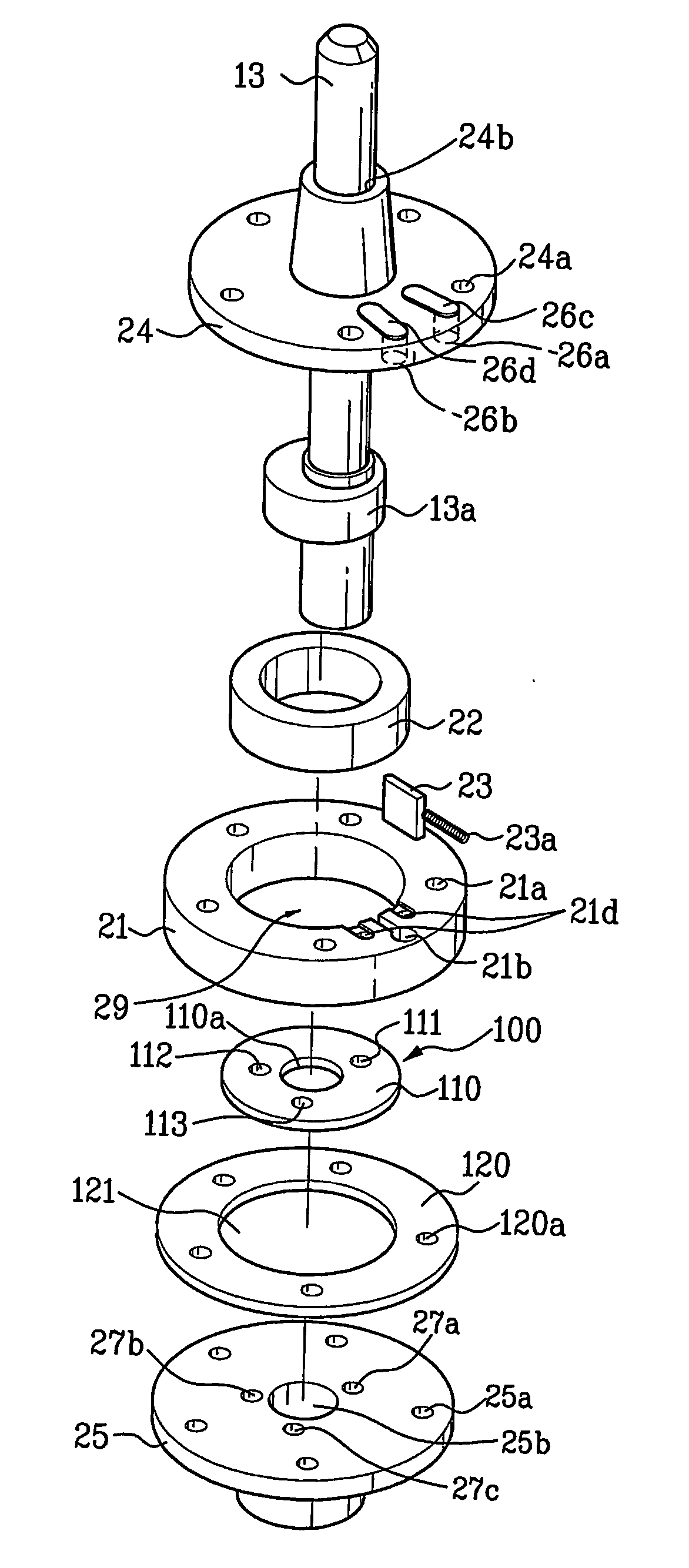
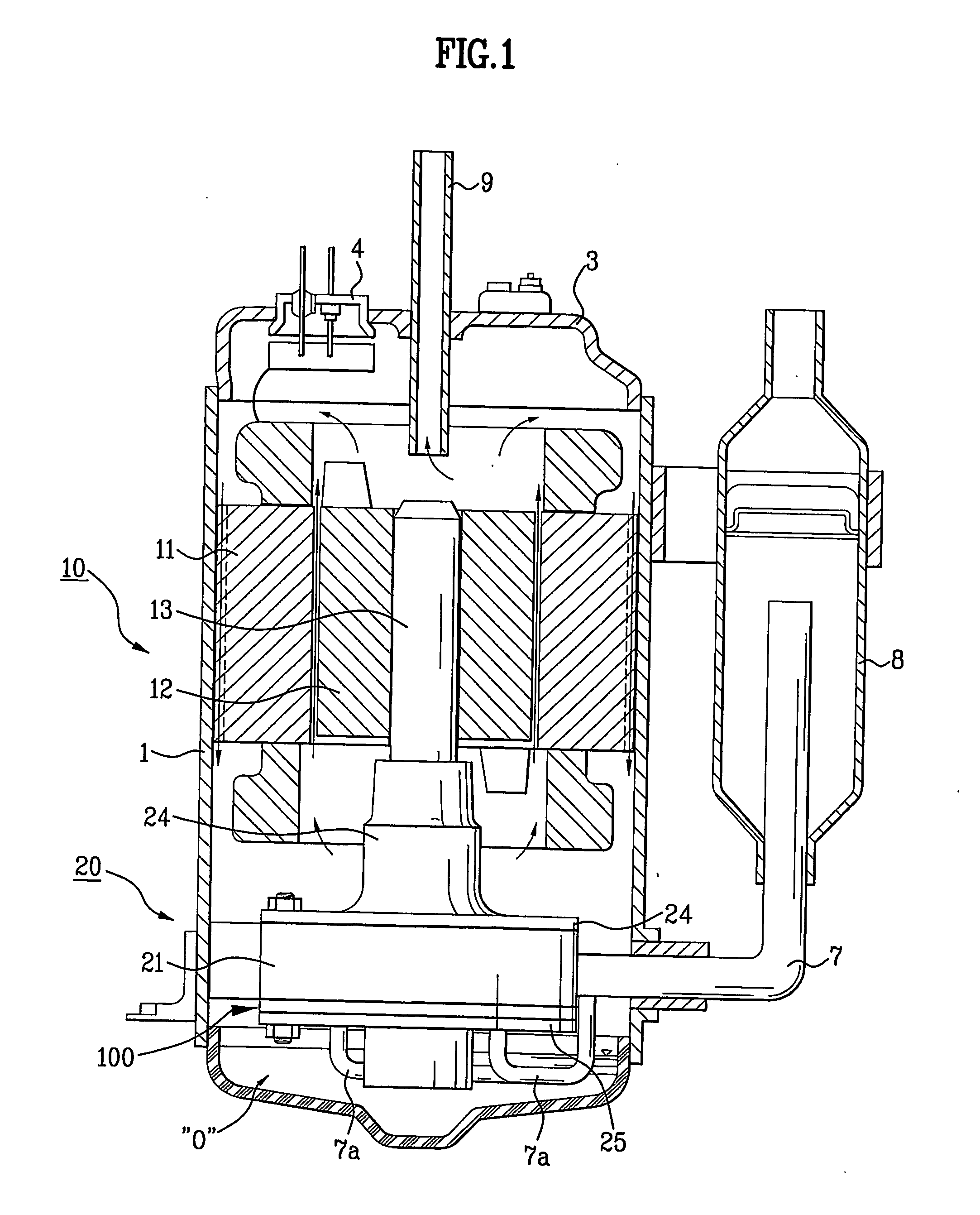
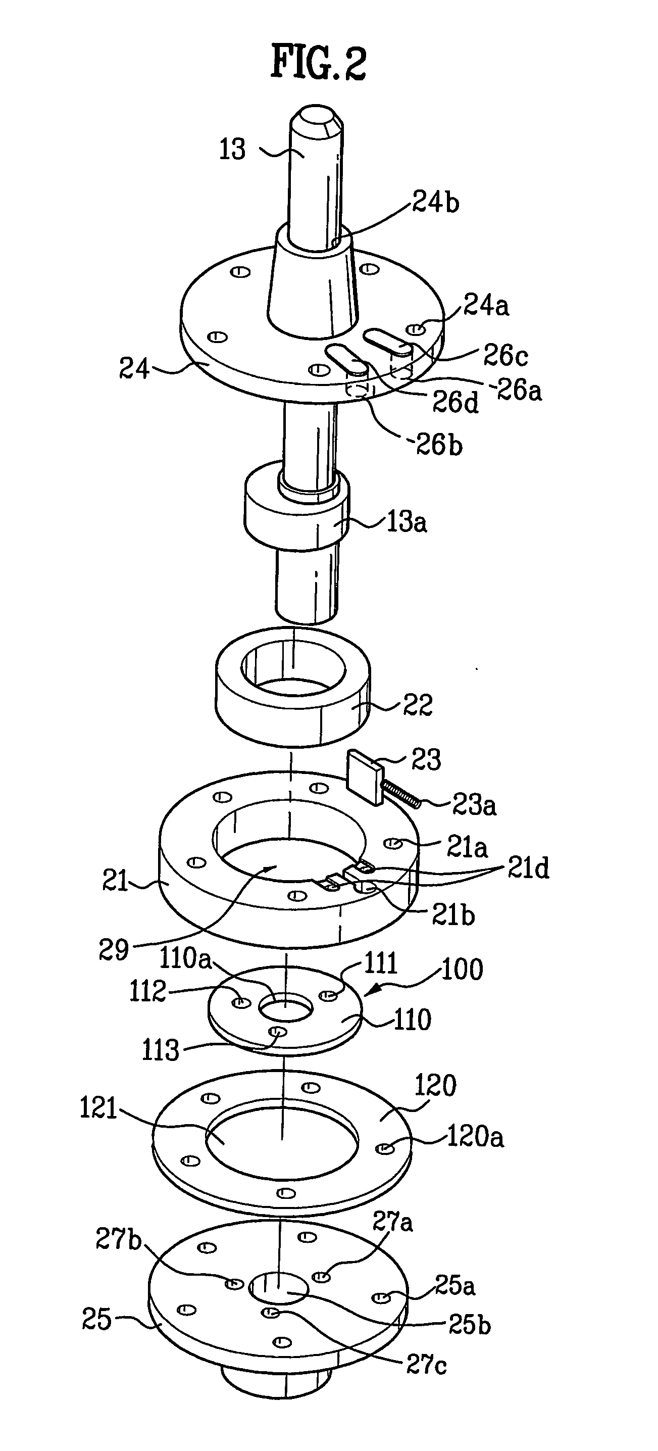
[0039]FIG. 1 is a partial longitudinal sectional view illustrating a rotary compressor according to an embodiment of the present invention, FIG. 2 is an exploded perspective view illustrating that a valve assembly that is not biased eccentrically is installed in the compressing unit of the rotary compressor of FIG. 1, and FIG. 3 is a sectional view illustrating the compressing unit of FIG. 2. An embodiment of the present invention will be described with reference to FIGS. 1 to 3.

[0040] As shown in FIG. 1, a rotary compressor of the present invention includes a case 1, a power generator 10 positioned in the case 1 and a compressing unit 20. Referring to FIG. 1, the power generat...


PUM


Abstract

Disclosed is a rotary compressor having two compression capacities. The rotary compressor includes: a driving shaft (13) being rotatable clockwise and counterclockwise, and having an eccentric portion (13a) of a predetermined size; a cylinder (21) forming a predetermined inner volume; a roller (22) installed rotatably on an outer circumference of the eccentric portion (13a) so as to contact an inner circumference of the cylinder (21), performing a rolling motion along the inner circumference and forming a fluid chamber (29) to suck and compress fluid along with the inner circumference; a vane (23) installed elastically in the cylinder to contact the roller (22) continuously; a first bearing (24) installed in the cylinder (21), for rotatably supporting the driving shaft (13); a second bearing (300) installed in the cylinder (21), for rotatably supporting the driving shaft (13) and guiding the fluid into the fluid chamber (29); discharge ports (26) communicating with the fluid chamber (29); and a valve assembly (400) having openings (411, 412) separated by a predetermined angle from each other, for allowing the openings (411, 412) to selectively introduce the fluid into the fluid chamber (29) through the second bearing (300) at a predetermined position of the fluid chamber (29) according to rotation direction of the driving shaft (13), the valve assembly (400) having a center (410a) which is eccentrically installed by a predetermined distance from a center of the cylinder (29).

Description

TECHNICAL FIELD [0001] The present invention relates to a rotary compressor, and more particularly, to a mechanism for changing compression capacity of a rotary compressor. BACKGROUND ART [0002] In general, compressors are machines that are supplied power from a power generator such as electric motor, turbine or the like and apply compressive work to a working fluid, such as air or refrigerant to elevate the pressure of the working fluid. Such compressors are widely used in a variety of applications, from electric home appliances such as air conditioners, refrigerators and the like to industrial plants. [0003] The compressors are classified into two types according to their compressing methods: a positive displacement compressor, and a dynamic compressor (a turbo compressor). The positive displacement compressor is widely used in industry fields and configured to increase pressure by reducing its volume. The positive displacement compressors can be further classified into a reciproc...

Claims


Application Information

Patent Timeline
IPC IPC(8): F04C18/356F04C28/04F04C18/00F04C28/14
CPCF04C18/3564F04C28/14F04C28/04Y10T137/86638F04C18/00
Inventor BAE, JI YOUNGROH, CHUL GIPARK, KYOUNG JUNJANG, CHANG YONGKIM, JONG BONGKO, YOUNG HWAN
Owner LG ELECTRONICS INC
Why Eureka
Try Eureka