Stent Positioning Using Inflation Tube

Inactive Publication Date: 2007-12-06
F D CARDIO
View PDF39 Cites 107 Cited by
  • Summary
  • Abstract
  • Description
  • Claims
  • Application Information

AI Technical Summary

Benefits of technology

[0008] An aspect of some embodiments of the invention concerns a catheter with a balloon, for example for expanding a stent. In an embodiment, the catheter comprises a relatively stiff inflation tube inside an outer sheath, and the inflation tube can move relative to the outer sheath. The catheter as a whole is used for coarse positioning of the balloon in a blood vessel or other lumen, as in conventional catheters. For example, the catheter is pushed and sometimes twisted by hand, while its progress is followed by using medical imaging device such as a fluoroscope. For fine adjustment in the position of the balloon, the inflation tube is used to push or pull the balloon, while keeping the outer sheat

Problems solved by technology

Emboli can also cause clogging of blood vessels.
Placing the stent at a wrong position, for example not directly over the plaque, can increase the chance of complications such as stent thrombosis and restenosis.
However, it is often difficult for physicians to precisely control the position of a catheter, even when imaging techniques make it possible to tell exactly where the stent is, relat

Method used


Image

  • Stent Positioning Using Inflation Tube
  • Stent Positioning Using Inflation Tube
  • Stent Positioning Using Inflation Tube

Examples


Example

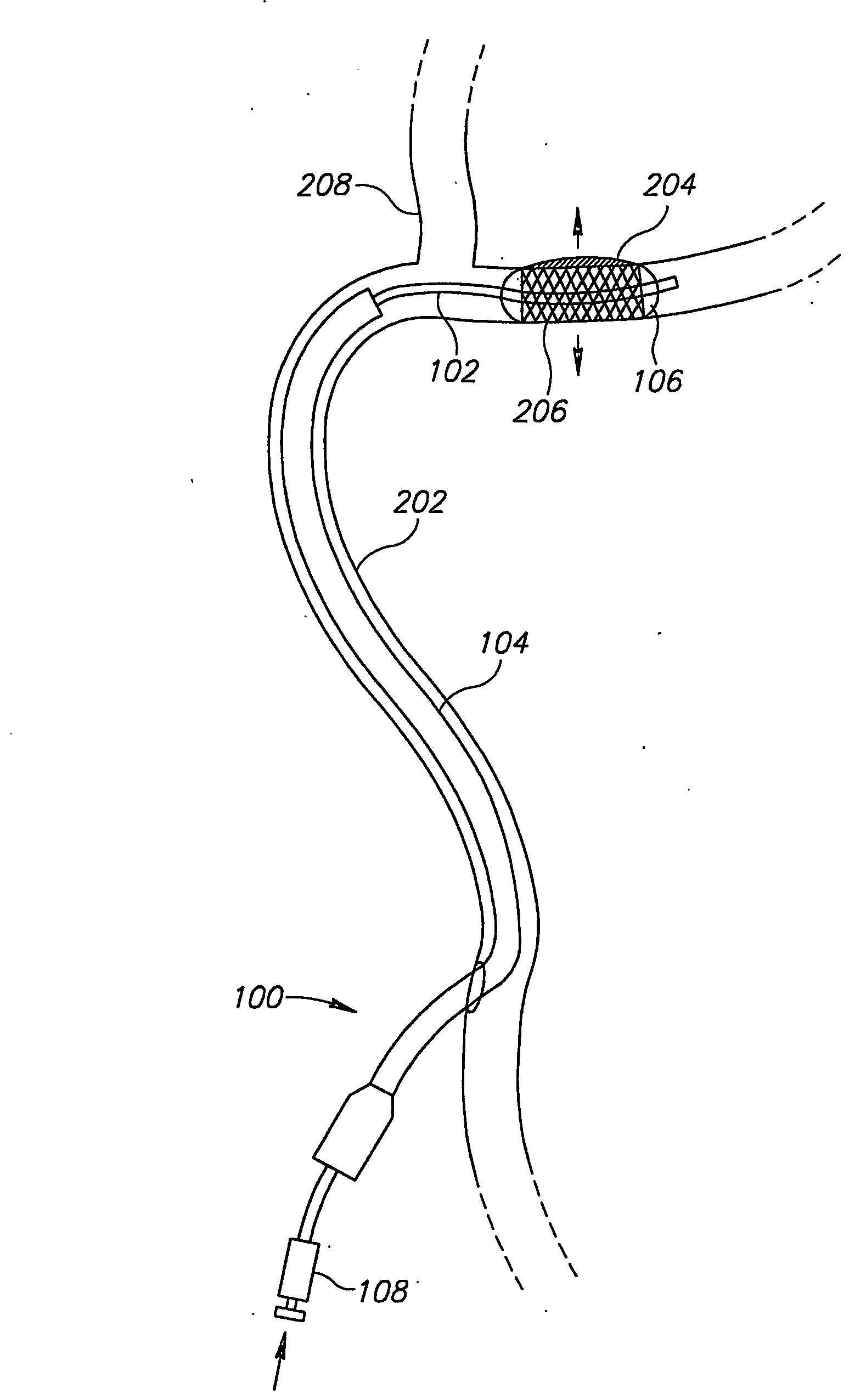
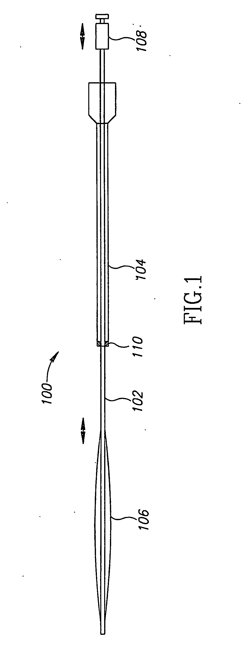
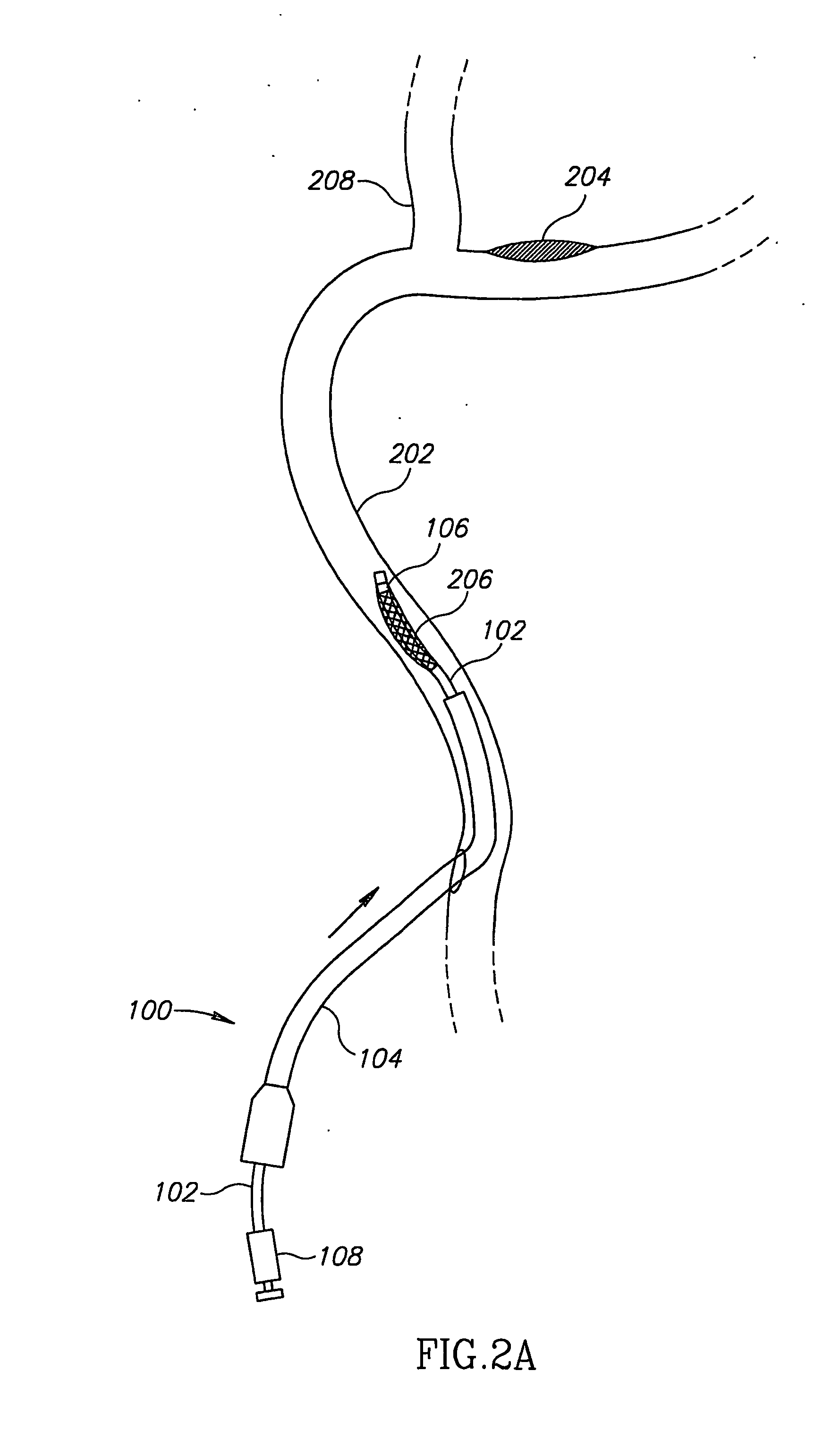
[0055]FIG. 1 shows an intravascular balloon catheter 100, in accordance with an embodiment of the invention, comprising an inflation tube 102 surrounded by an outer sheath 104. There is a balloon 106 at the end of inflation tube 102, which is stiff enough so that the inflation tube can be used to push the balloon relative to the rest of the catheter, for fine adjustment in positioning the balloon.

[0056]FIG. 1 is not necessarily drawn to scale, and in particular, the outer sheath and inflation tube of catheter 100 are typically very much longer, relative to their diameter, than shown in FIG. 1. This is also true of the catheters in all the other drawings. Also, in FIG. 1 and in the other drawings, balloon 106 is shown in a somewhat inflated state, for clarity. In practice the balloon will be in a collapsed state, fitting fairly closely around the inflation tube, until it is in position and ready for inflating.

[0057] An inflation tube manipulator 108, outside the body, allows the in...


PUM


Abstract

A catheter adapted for performing a task at a location inside a lumen, the catheter comprising: a) an outer sheath; b) a balloon capable of inflating inside the lumen when the catheter reaches the location; and c) a balloon inflation tube, which is attached to the balloon and carries a fluid which causes the inflating of the balloon, said balloon inflation tube running through the outer sheath, movable relative to the outer sheath, and stiff enough so that it can be used to push and pull the balloon relative to the outer sheath.

Description

RELATED APPLICATIONS [0001] This application claims priority from and is a continuation-in-part of PCT application PCT / IL03 / 00995 filed on Nov. 25, 2003, which designates the United States, and is also a continuation-in-part of U.S. application Ser. No. 10 / 303,064, filed on Nov. 25, 2002, the disclosures of which are incorporated herein by reference. This application also incorporates by reference a patent application titled “Catheter Drive,” agent's file reference 378 / 04070, filed on May 27, 2004, the same day as the current application, at the United States Patent and Trademark Office.FIELD OF THE INVENTION [0002] The field of the invention is catheters, particularly for positioning and advancing stents and other medical devices in blood vessels and other lumens of the body. BACKGROUND OF THE INVENTION [0003] Blood vessels can suffer from various diseases, in particular arteriosclerosis, in which obstructions form in a lumen of a blood vessel, narrowing or clogging it. Emboli can ...

Claims


Application Information

Patent Timeline
IPC IPC(8): A61M25/10A61FA61F2/84A61M25/00
CPCA61F2/958A61M25/0021A61M25/1006A61M2025/0681A61M2025/0004A61M2025/0063A61M2025/0175A61M25/104
Inventor WACHSMAN, ODEDCHERMONI, ISRRAEL
Owner F D CARDIO
Why Eureka
Try Eureka