Articulated Bone Screw

a bone screw and articulation technology, applied in the field of bone screws, can solve the problem of inability to transfer torque, and achieve the effect of reducing the design of the construction and achieving a greater degree of freedom of the bone screw

Inactive Publication Date: 2007-12-06
DEPUY SYNTHES PROD INC
View PDF31 Cites 61 Cited by
  • Summary
  • Abstract
  • Description
  • Claims
  • Application Information

AI Technical Summary

Benefits of technology

[0005] The advantages, achieved by the invention, can be seen to lie essentially therein that, due to the inventive bone screw, bones can be connected with one another in such a manner that a certain bending and, with that, mobility with respect to one another becomes possible.
[0006] In the case of a special embodiment, the cardan joint consists of a classical universal joint. In the case of a different embodiment, the cardan-like joint consists of a ball joint with a ball head, which has a ...

Problems solved by technology

However, the transfer of torques is not possible with...

Method used


Image

  • Articulated Bone Screw
  • Articulated Bone Screw
  • Articulated Bone Screw

Examples


Embodiment Construction

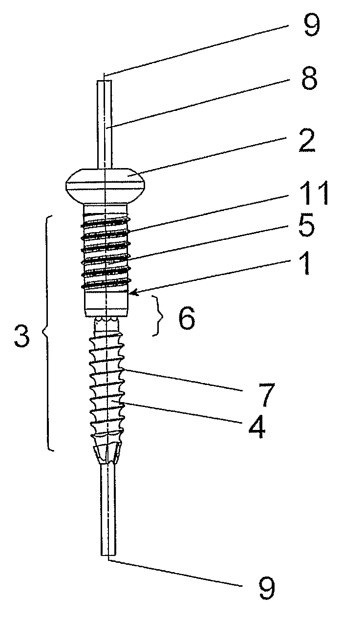
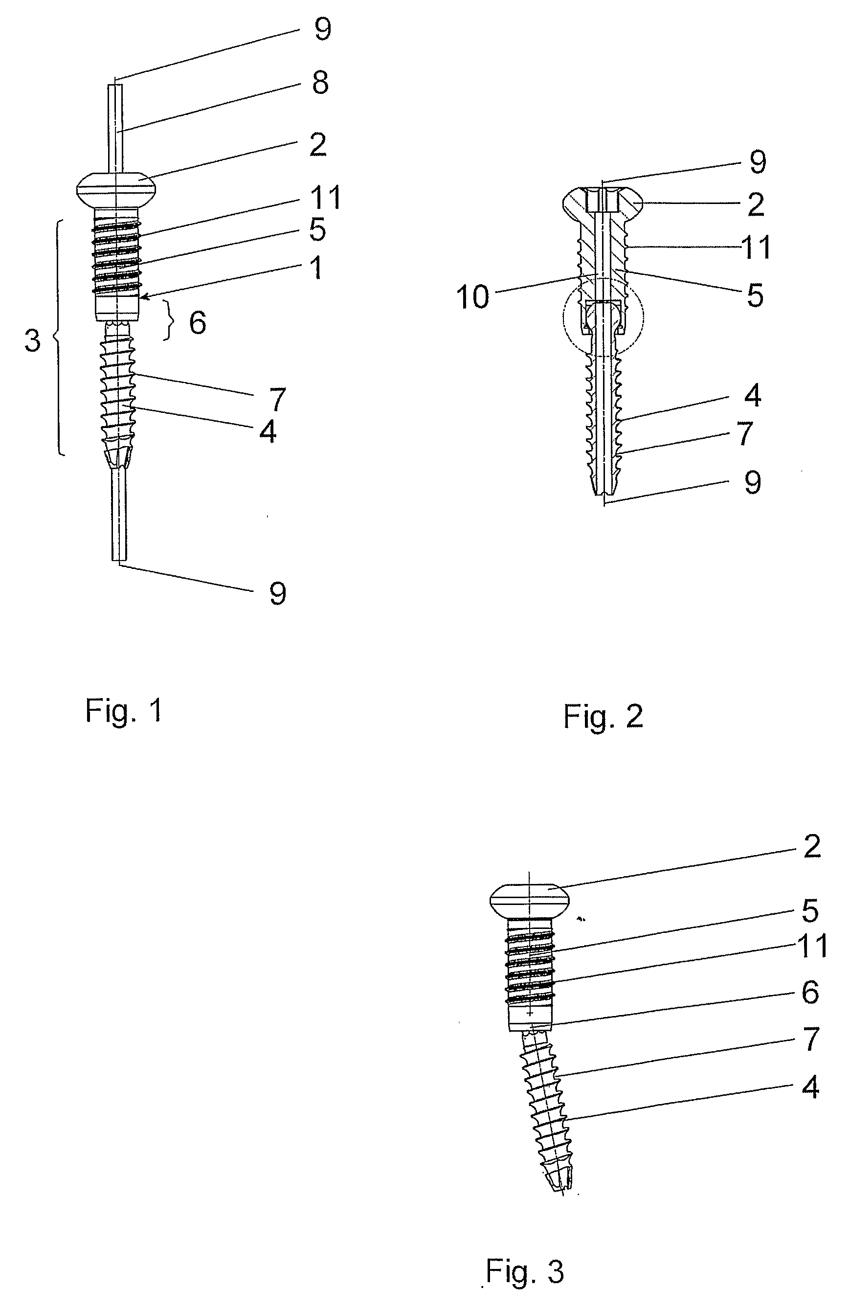
[0022] The inventive bone screw 1, shown in FIGS. 1-3, has a head part 2, a shaft 3, a longitudinal axis 9 and a continuous central cannulation 10. The shaft 3 consists of a proximal section 5 with an external thread 11, adjoining the head part 2, and a distal section 7 with an external thread 4, fastened thereto by means of a cardan joint 6, for introduction into the bone. If a Kirschner wire 8 (FIG. 1) is introduced into the central cannulation 10 (FIG. 2), the cardan joint 6 is blocked, so that the bone screw 1 can no longer be bent, as indicated in FIG. 1.

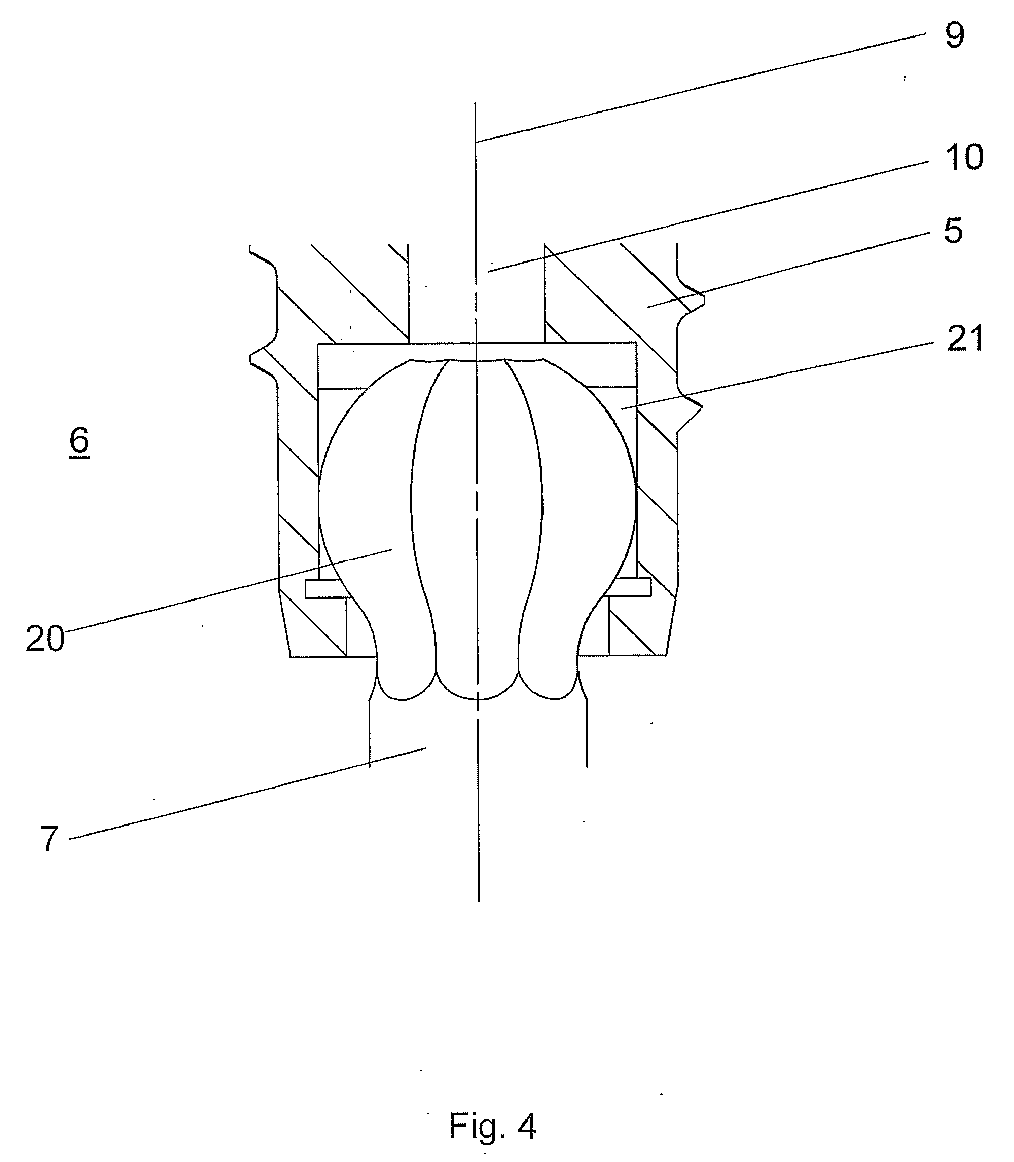
[0023] As shown in detail in FIG. 4, the cardan joint 6 consists of a ball joint with a ball head 20 and a ball socket, which is accommodated in the proximal section 5. The ball head 20 has an octagonal cross section and the ball socket has a correspondingly adapted, octagonal geometry, which is suitable for accommodating the cross section of the ball head 20. This geometry permits the bone screw 1 to be rotated also in the be...


PUM


Abstract

The bone screw has a head, a shaft and a longitudinal axis. The shaft comprises a proximal section adjacent to the head and a distal section secured to the proximal section by a cardan or cardan-like joint, the distal section being suitable for introduction into the bone and being provided with an outer thread. The bone screw can be bent in all directions relative to its longitudinal axis, while retaining its axial rigidity and fully transmitting a couple without the need for additional means.

Description

FIELD OF THE INVENTION [0001] The invention relates to a bone screw. BACKGROUND OF THE INVENTION [0002] U.S. Pat. No. 4,959,064 of ENGLEHARDT discloses a bone screw with a spring part. The spring part of the bone screw endows it with a certain axial elasticity (axial compression or distraction), as well as a certain torsion and also a certain radial bending in all direction. Accordingly, this known bone screw will prevent only a decrease in the compressive effect of the screw. [0003] The EP-A 1,273,269 of MÜCKTER discloses a bone screw with an elastic shaft. The elasticity of this construction as described in various embodiments. Here also, the elastic connection of the screw provides a certain axial elasticity. However, the transfer of torques is not possible without the help of further stabilizing instruments or implants. SUMMARY OF THE INVENTION [0004] It is an object of the invention to create a bone screw, which can be bent in all directions relative to its longitudinal axis wh...

Claims


Application Information

Patent Timeline
IPC IPC(8): A61B17/58A61B17/86
CPCA61B17/8685A61B17/863A61B17/86
Inventor NIEDERBERGER, ALFREDVAN DER WERKEN, CHRISTIAN
Owner DEPUY SYNTHES PROD INC
Why Eureka
Try Eureka