Stator arrangement

a stator and arrangement technology, applied in the direction of cooling/ventilation arrangement, wind energy generation, electrical equipment, etc., can solve the problems of high temperature gradient, high temperature gradient, high temperature gradient, etc., and achieve the effect of simple constructive design and good cooling performan

Inactive Publication Date: 2012-09-13
SIEMENS GAMESA RENEWABLE ENERGY AS
View PDF5 Cites 5 Cited by
  • Summary
  • Abstract
  • Description
  • Claims
  • Application Information

AI Technical Summary

Benefits of technology

[0006]Hence, it is the object of the invention to provide an approved stator arrangement, particularly in regard of good cooling performance and simple constructive design.
[0010]Hence, the inventive principle essentially teaches an alternating arrangement of sets of stator windings and cooling means within the respective stator slots of multi-layer stator configurations. In such a manner, a respective cooling means essentially has two contact sites, i.e. a lower and an upper contact site with the respective adjacently disposed sets of stator windings giving rise to an improved cooling performance and cooling efficiency. Aside, the assembly of the stator is eased, since the respective sets of stator windings and cooling means merely have to be inserted in the respective stator slots in successive manner, that is one after another.
[0012]The duct-like pipe is preferably made of a thermally conductive material, particularly a metal, especially aluminium, copper or stainless steel. Hence, the duct-like pipe offers good mechanical stability, good thermal properties, anti-corrosive properties and may be shaped in diverse geometrical shapes. Of course, other materials having a like spectrum of properties such as polymers filled with thermally conductive particles may be applicable as well.
[0014]In a further embodiment of the invention, the inlet and outlet of the duct-like pipes are disposed on the same face side of the stator yoke. In such a manner, both inlets and outlets are easily accessible which offers advantages in terms of connecting the duct-like pipes to a cooling system for instance. Aside, service and repair are easily executable.
[0015]It is of advantage when the ends of at least one set of stator windings are bent in radially upward or downward direction. In such a manner, the insertion and installation of the cooling means, that is preferably the duct-like pipes is facilitated since the respective parts of the stator are easily accessible. Preferably, the ends of adjacently disposed sets of stator windings are bent in opposite directions which further enhances the accessibility to the duct-like pipes.
[0016]It is also thinkable that the course of the at least one cooling means at least partially corresponds to the course of the at least one cooling means at least partially corresponds to the course of at least one respective set of stator windings. With the shape of the respective set of stator windings and the shape of the cooling means being essentially the same, the contact area between the respective set of stator windings and the cooling means may be enhanced and thus, the cooling performance further improved. Thereby, even the area of the ends of the respective stator windings, i.e. the end windings is provided with sufficient cooling.

Problems solved by technology

The operation of an electric machine such as a generator for instance is usually accompanied by great heat densities leading to high temperature gradients within the stator.
That is, the problem of excessive heat particularly occurring in the area of the stator, namely caused by so called copper losses, has to be encountered.
Thereby, the contact surface between the cooling means and the stator windings is limited, thus thermal exchange and cooling performance is comparatively low.
Yet, this principal is considered as constructively complex and may lead to disadvantages especially in cases of failure since the cooling means are hardly to separate from the stator windings.

Method used


Image

  • Stator arrangement
  • Stator arrangement
  • Stator arrangement

Examples


Embodiment Construction

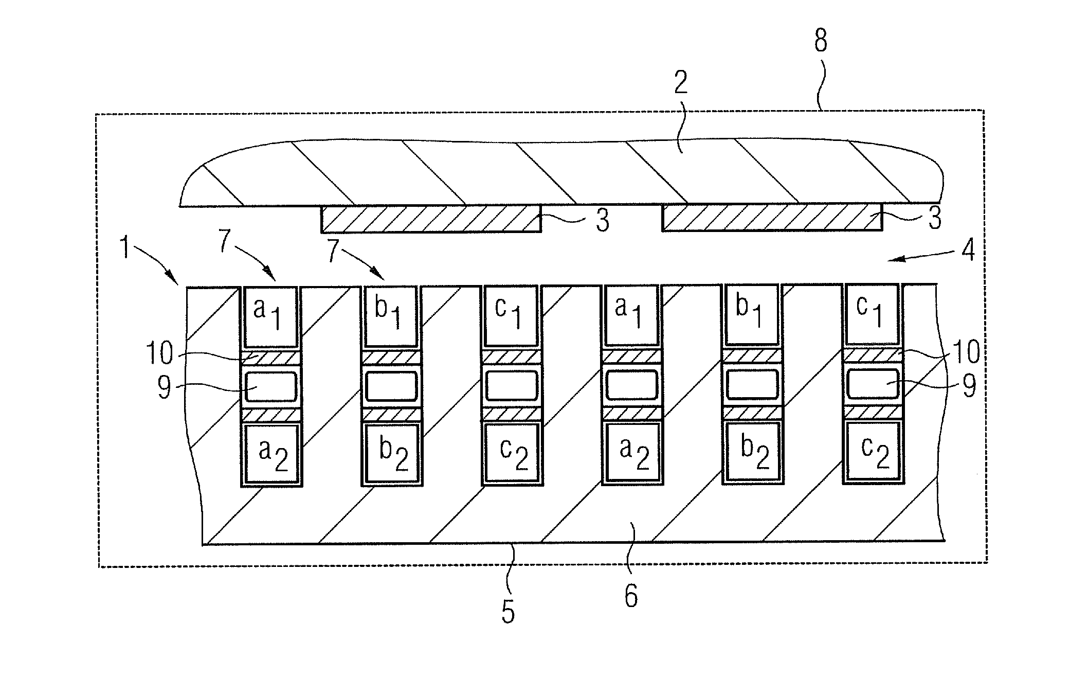
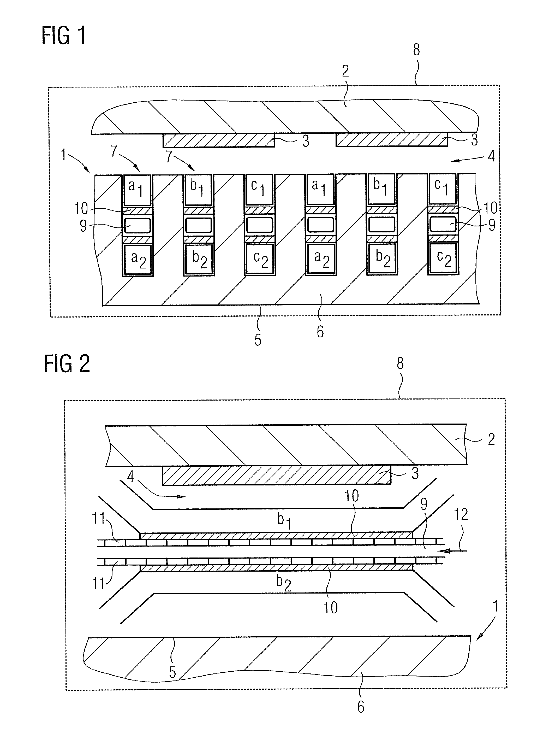
[0024]FIG. 1 shows a principle cut-out front view of a stator arrangement 1 according to an exemplary embodiment of the present invention and a respective rotor 2. The rotor 2 comprises several permanent magnets 3 and surrounds the stator arrangement 1, whereby an air gap 4 is provided between the stator arrangement 1 and the rotor 2. Generally, a reverse arrangement, that is the stator arrangement 1 surrounding the rotor 2 is applicable as well.

[0025]The stator arrangement 1 comprises a stator 5 having a stator yoke 6 particularly built of several laminated stacked metal plates (not shown). The stator yoke 6 comprises a number of axially extending stator slots 7.

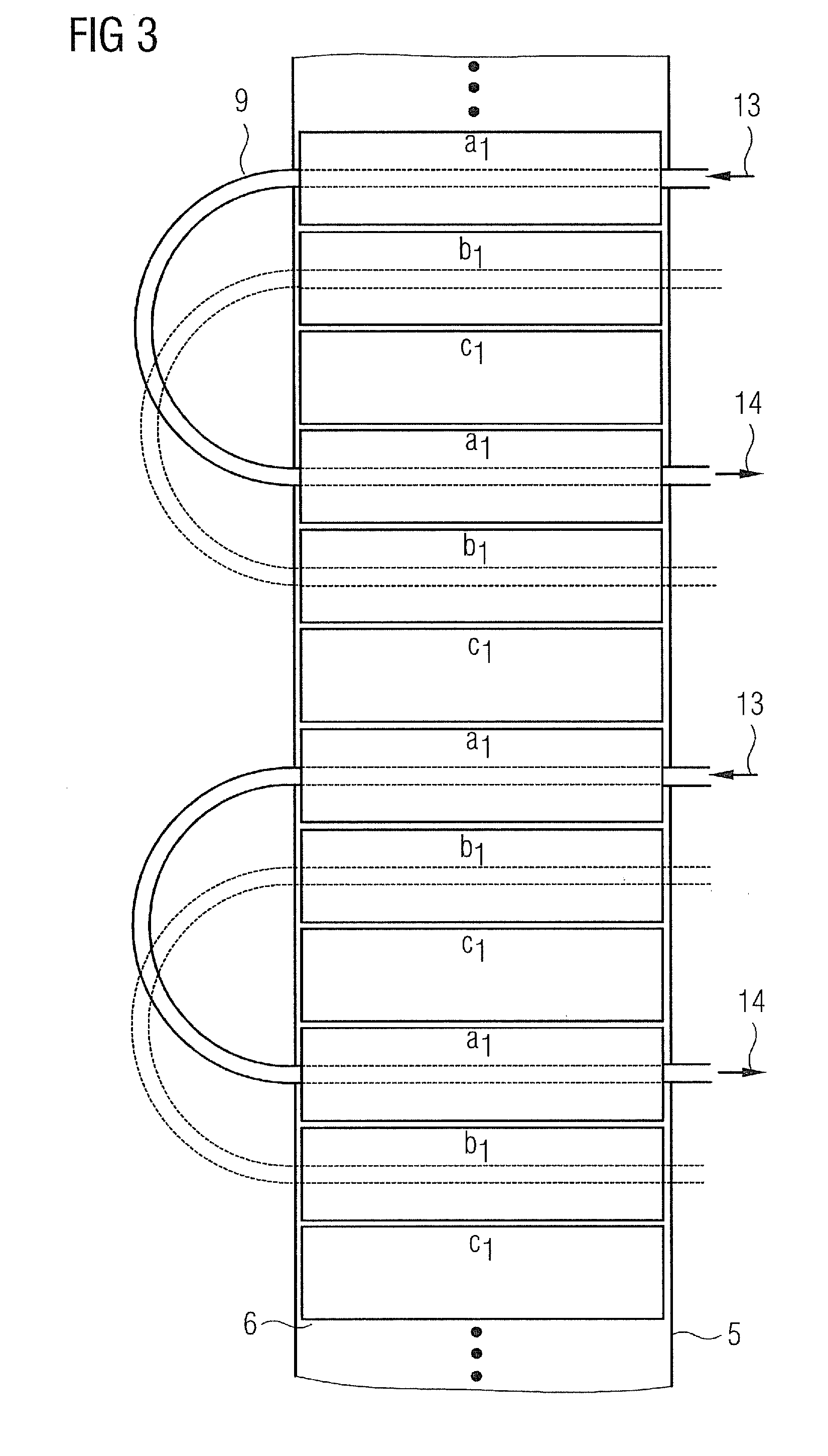
[0026]The stator arrangement 1 and the rotor 2 are components of a three-phase electric machine 8 indicated by the rectangle. The electric machine 8 has a double-layer configuration, that is each slot 7 comprises two layers or sets of stator windings.

[0027]The notation of the respective sets of stator windings is as follows...


PUM


Abstract

A Stator arrangement for an electric machine includes a stator having a stator yoke with a plurality of stator slots. Each stator slot accommodates at least two adjacently disposed sets of stator windings and at least one cooling device, wherein the at least one cooling device is disposed between the respective adjacently disposed sets of stator windings.

Description

CROSS REFERENCE TO RELATED APPLICATIONS[0001]This application claims priority of European Patent Office application No. 11157464.6 EP filed Mar. 9, 2011. All of the applications are incorporated by reference herein in their entirety.FIELD OF INVENTION[0002]The invention relates to a stator arrangement for an electric machine, comprising a stator having a stator yoke with a number of stator slots, with each stator slot accommodating at least two adjacently disposed sets of stator windings and at least one cooling means.BACKGROUND OF INVENTION[0003]The operation of an electric machine such as a generator for instance is usually accompanied by great heat densities leading to high temperature gradients within the stator. That is, the problem of excessive heat particularly occurring in the area of the stator, namely caused by so called copper losses, has to be encountered. Hence, it is known to provide respective stator arrangements with respective cooling means in order to provide prope...

Claims


Application Information

Patent Timeline
Patent Type & Authority Applications(United States)
IPC IPC(8): H02K3/24
CPCY02E10/725H02K3/24Y02E10/72
Inventor KIMIABEIGI, MOHAMMAD
Owner SIEMENS GAMESA RENEWABLE ENERGY AS
Why Eureka
Try Eureka