Expandable element

a technology of expanding elements and implants, applied in the field of expanding implants, can solve the problems of relative complexity of the delivery procedure, large entry hole in the body required to insert the device, and severe pain

Inactive Publication Date: 2007-12-06
KYPHON
View PDF99 Cites 345 Cited by
  • Summary
  • Abstract
  • Description
  • Claims
  • Application Information

AI Technical Summary

Benefits of technology

[0110] In a preferred embodiment of the invention, the spacer comprises at least...

Problems solved by technology

Material that exits the disc may press against the spinal cord, causing severe pain.
One disadvantage of some of known fusion devices is that a relatively large entry hole in the body is required to insert the device.
Another disadvantage of some known fusion devices is lies in a relative com...

Method used


Image

  • Expandable element
  • Expandable element
  • Expandable element

Examples


embodiment

Ring Locking Embodiment

[0276]FIGS. 19A-19C illustrate a ring-based locking mechanism, in accordance with a preferred embodiment of the invention. A cage 1070 and a bolt 1072 are locked together using a ring 1075, that matches a groove 1077 formed in bolt 1072, thereby locking the bolt against an end-cap 1076 of spacer 1070.

[0277] In FIG. 19A, the spacer is unexpanded. As a pusher 1079 is advanced, spacer 1070 axially contracts and radially expands. Concurrently ring 1075 is advanced towards spacer 1070.

[0278] In FIG. 19B, ring 1075 contracts into groove 1077, thereby locking the spacer.

[0279]FIG. 19C illustrates an exemplary ring 1075, which is preferably formed of a super-elastic material, such as Nitinol, however, this is not required.

Tube Cross-Section

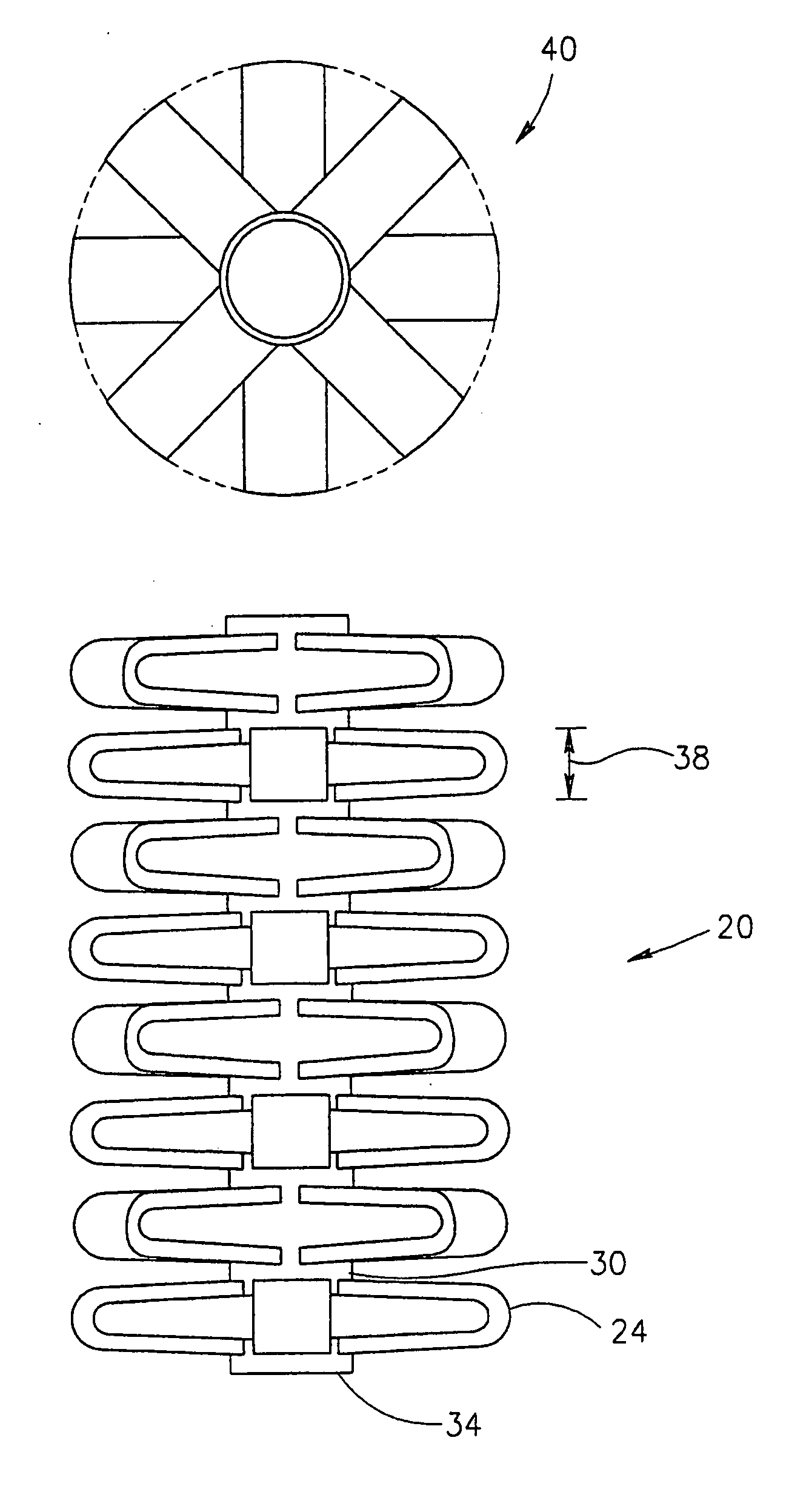
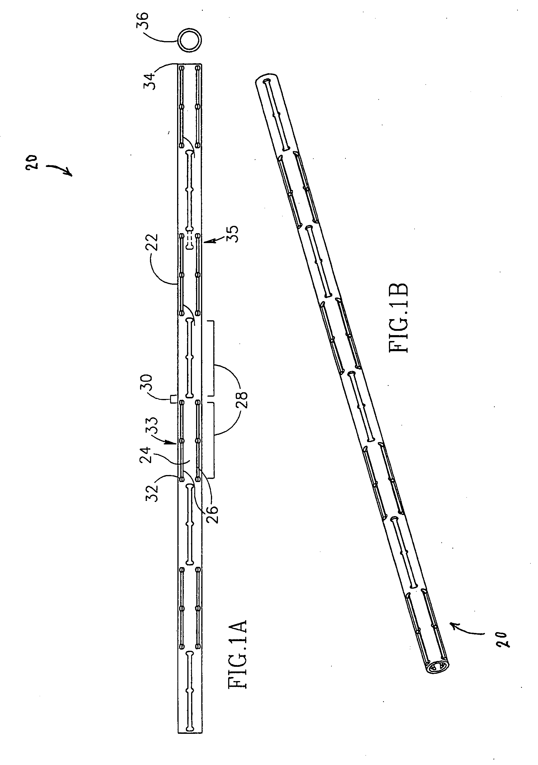
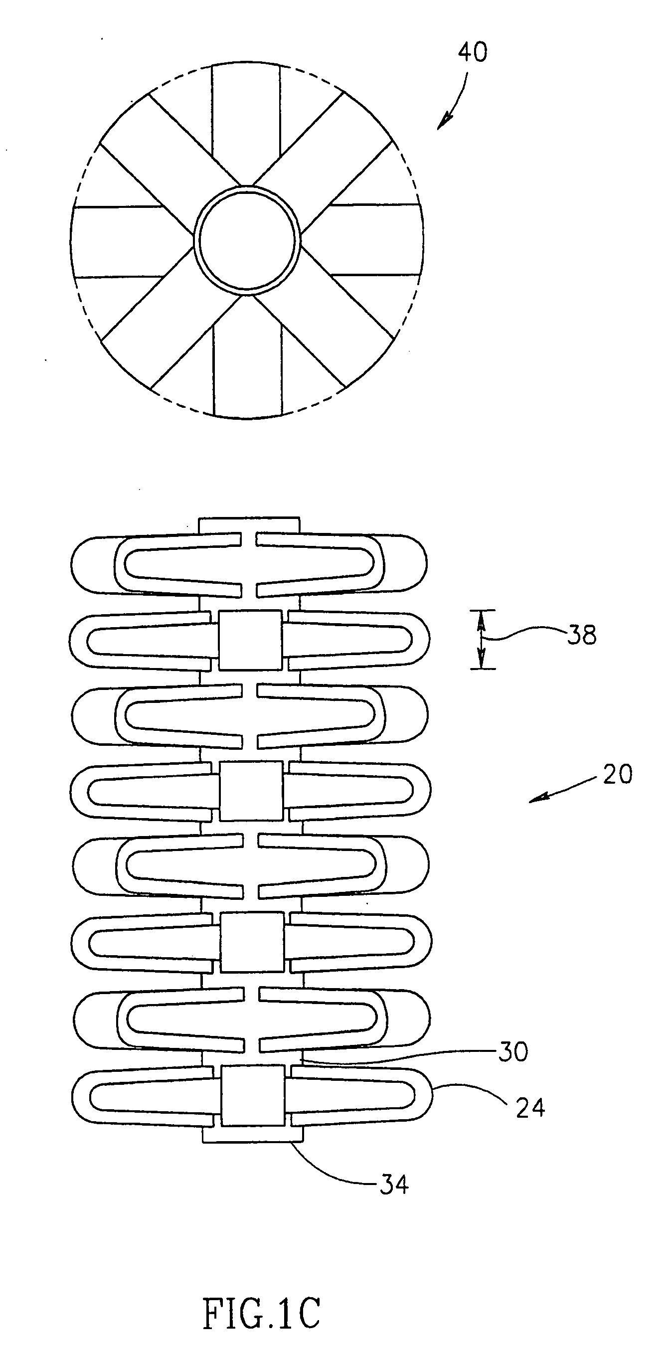
[0280] In a preferred embodiment of the invention, the cross-section of tube 22 (FIGS. 1A-1D) is circular. Alternatively, other cross-section are used, for example, polygon cross-sections, such as a triangle or a square. Prefe...


PUM

PropertyMeasurementUnit
Lengthaaaaaaaaaa
Flow rateaaaaaaaaaa
Diameteraaaaaaaaaa

Abstract

An expandable spacer, comprising: an axial tube having a surface, a proximal end and a distal end and a length, wherein, said surface defines a plurality of slits, said plurality of slits defining at least two axially displaced extensions, such that when said tube is axially compressed, said extensions extend out of said surface and define a geometry of an expanded spacer. Preferably the spacer is adapted to be inserted between two spinal vertebrae of a human.

Description

RELATED APPLICATIONS [0001] This application is a continuation-in-part of: [0002] (a) U.S. patent application Ser. No. 11 / 042,546, filed Jan. 24, 2005, pending, which is a continuation of U.S. patent application Ser. No. 09 / 890,172 filed on Jul. 25, 2001, which is a 371 of PCT application PCT / IL00 / 00058, filed on Jan. 27, 2000 and published as WO 00 / 44319; [0003] And which claims priority from Israeli Patent Application No. 128261, filed on Jan. 27, 1999; [0004] (b) U.S. patent application Ser. No. 10 / 182,352 filed Mar. 17, 2003, pending; which is a 371 of PCT / IL00 / 00471, filed Aug. 3, 2000 and published as WO 01 / 54598, and which is a continuation-in-part of [0005] (1) PCT application PCT / IB98 / 00523, filed Mar. 6, 1998, published as WO 98 / 38918, which designates the U.S.; [0006] (2) U.S. patent application Ser. No. 09 / 890,320 filed Jul. 25, 2001 which is a 371 of PCT application PCT / IL00 / 00055 filed Jan. 27, 2000, and claiming the benefit under 119(e) of: [0007] (i) 60 / 120,184, file...

Claims


Application Information

Patent Timeline
IPC IPC(8): A61F2/44A61B17/56A61B17/00A61B17/02A61B17/16A61B17/22A61B17/32A61B17/58A61B17/72A61C8/00A61F2/00A61F2/02A61F2/28A61F2/30A61F2/46A61F2/48C21D1/26C21D1/34C21D1/38C22F1/00C22F1/18C22F3/00
CPCA61B17/00234A61B17/1637A61B17/1671A61B17/22032A61B17/7266A61B2017/00261A61B2017/0256A61B2017/22034A61B2017/320004A61B2017/320008A61B2017/320048A61F2/28A61F2/30724A61F2/30744A61F2/30767A61F2/30771A61F2/3094A61F2/441A61F2/442A61F2/4455A61F2/446A61F2/4611A61F2/4657A61F2002/0086A61F2002/009A61F2002/2817A61F2002/2835A61F2002/30004A61F2002/30014A61F2002/30052A61F2002/30079A61F2002/30082A61F2002/30093A61F2002/30097A61F2002/30113A61F2002/3013A61F2002/30131A61F2002/30136A61F2002/30153A61F2002/30154A61F2002/30156A61F2002/30158A61F2002/30224A61F2002/30235A61F2002/30291A61F2002/30324A61F2002/30326A61F2002/30327A61F2002/30329A61F2002/30405A61F2002/30451A61F2002/30454A61F2002/30462A61F2002/30484A61F2002/30485A61F2002/30495A61F2002/305A61F2002/30507A61F2002/3051A61F2002/3052A61F2002/30545A61F2002/30546A61F2002/3055A61F2002/30579A61F2002/30594A61F2002/30596A61F2002/30611A61F2002/30616A61F2002/30617A61F2002/30668A61F2002/3067A61F2002/30677A61F2002/30774A61F2002/30777A61F2002/30785A61F2002/30787A61F2002/30841A61F2002/30892A61F2002/30906A61F2002/3093A61F2002/30932A61F2002/30971A61F2002/4415A61F2002/4475A61F2002/448A61F2002/4485A61F2002/4619A61F2002/4623A61F2002/4627A61F2002/4635A61F2002/4638A61F2002/4649A61F2002/4658A61F2002/4677A61F2002/48A61F2210/0019A61F2210/0028A61F2210/009A61F2210/0095A61F2220/0025A61F2220/0058A61F2220/0075A61F2230/0004A61F2230/0006A61F2230/001A61F2230/0013A61F2230/0019A61F2230/0021A61F2230/0023A61F2230/0026A61F2230/0069A61F2230/0091A61F2240/001A61F2250/0001A61F2250/0002A61F2250/0007A61F2250/001A61F2250/0012A61F2250/0014A61F2250/0018A61F2250/0036A61F2250/0037A61F2250/0039A61F2250/0043A61F2250/0063A61F2250/0097A61F2310/00017A61F2310/00023Y10S606/91A61F2002/30092A61F2002/30604A61F2002/30593A61F2/4603A61F2/48A61F2/02
Inventor GLOBERMAN, ORENBEYAR, MORDECHAYSHAVIT, RONEN
Owner KYPHON
Why Eureka
Try Eureka