Air-inflated mattress

Active Publication Date: 2007-12-13
INTEX RECREATION
View PDF39 Cites 26 Cited by
  • Summary
  • Abstract
  • Description
  • Claims
  • Application Information

AI Technical Summary

Benefits of technology

[0019] 1. improved evenness and outer look of the surface, due to adding a middle layer below the top layer, and fixing the anchor separators on the middle layer instead of fixing them on the top layer.
[0020] 2. said middle layer is fixed alternatively with said anchor separators, so that when the bladder constructed by the top and bottom layers and the outer shroud band is fully inflated with air, the concave points of the middle layer, formed by tension of the anchor separators via the joint portion, are covered by the top layer, fixed on the convex points between the anchor separators and middle layer joint spots. The concave points and convex points are balanced as the space of the cavities surrounded by them is inflated fully with air, therefore the surface of the air mattress is flat and the evenness of the mattress is improved greatly.
[0021] 3. more comfortable, due to several small air pockets formed between joint spots welding the top layer and the middle layer, and the communication of small air pockets in the inflatable bladder. When extra force is exerted on parts of the surface of the air mattress, the air in

Problems solved by technology

When the surface of the mattress is pressed down with extra force, the shroud band will be squeezed outwardly by the compressed air inside of the bladder, to form a crowned bump, further affecting the smoothness of the mattress.
As some part of the surface of the mattress is exerted with extra force, such as,

Method used


Image

  • Air-inflated mattress
  • Air-inflated mattress
  • Air-inflated mattress

Examples


Example

[0056] A second embodiment of the invention is described by reference to FIGS. 9, 10, 11 and 11A. As can be seen, there are no vent holes in the tops of anchor separators 3 and there are no riser vent holes in the sides of middle shroud 6. There are only two vent holes 52 and 53, in one side of inner shroud 5, for air to pass from main bladder A into sub-chamber B. In addition, air passes into the space between top layer 1 and middle layer 2 to fill air pockets C by passing around and over the outer edges of middle layer 2, which edges are not welded to top layer 1. Air enters sub-chambers B-1 by gaps at the air inlet. FIG. 11A shows the pattern of side sub-chambers B1 as seen on the surface of outer shroud 4. In this embodiment, the air moves in and out much more slowly than in embodiment one, making it a stiffer mattress.

Example

[0057] A third embodiment of the invention is described by reference to FIGS. 12, 13 and 14 in which middle layer 2 has a plurality of riser vents 54 adjacent to the joint points 56 of anchor separators 3 to middle layer 2. In addition there are a plurality of riser vent holes 58 and 60 in inner and middle shrouds 5 and 6, but only in alternating side sub-chambers B1 where shrouds 5 and 6 are joined. Riser vents 62 provide airflow between bladder A and subchamber B. This embodiment allows air to flow more quickly than the second embodiment but not as quickly as embodiment one.

[0058]FIGS. 15 and 16 show the embodiment of FIG. 4 and show inflation pump 65 set into a housing in the side of shroud 4 of the mattress. Electrical line 66 with a plug (not shown) is connected to pump 65. The other side of the mattress has an optional valve 67 which may be opened to inflate or deflate the mattress.

Example

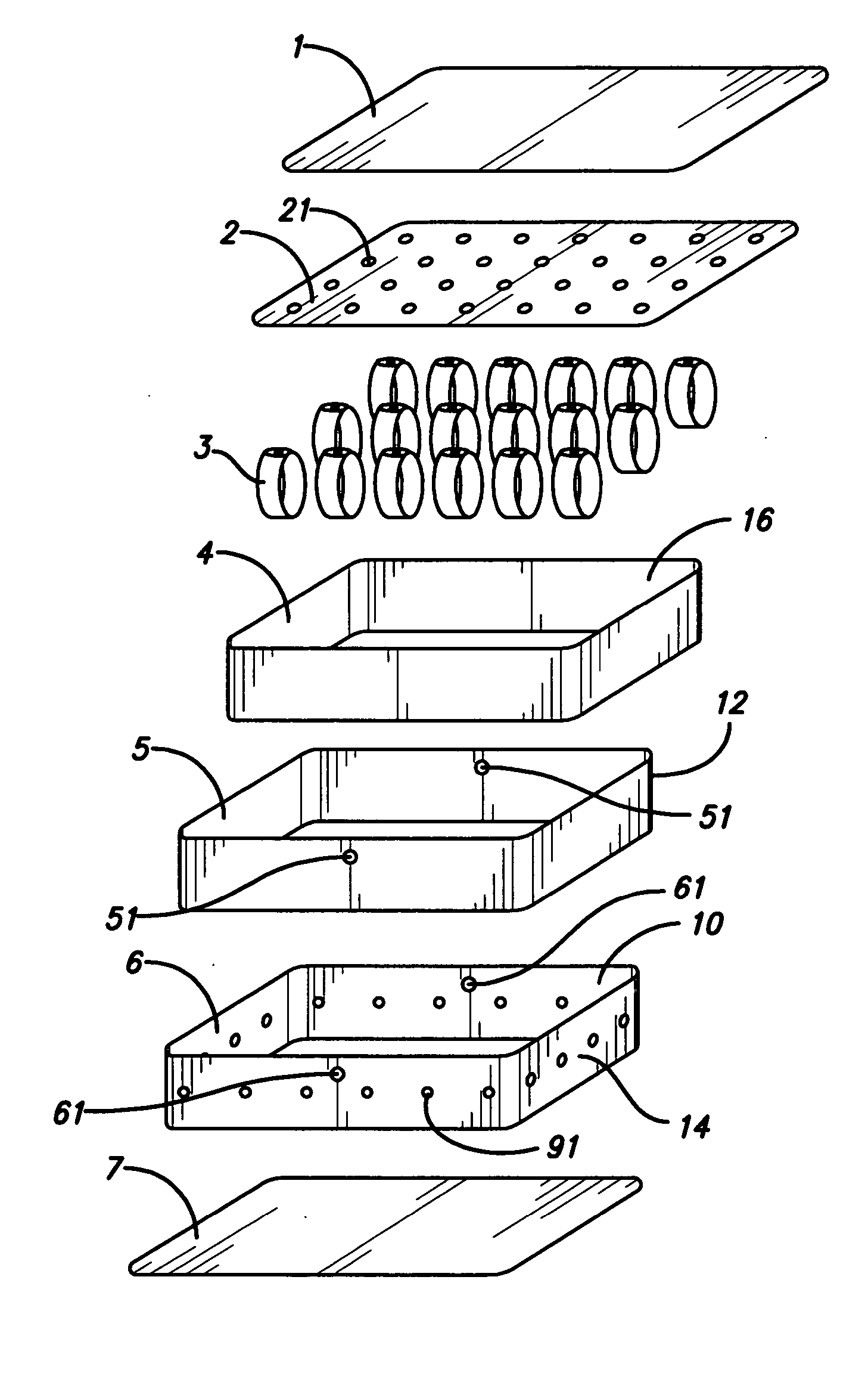
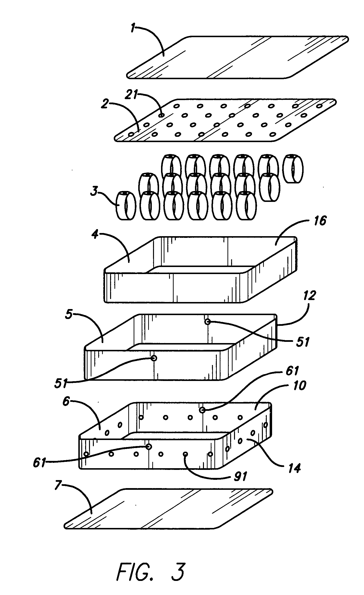
[0059] A fourth embodiment is shown in FIGS. 17 through 21. This embodiment comprises a double mattress, having an upper chamber 70 and a lower chamber 72. Upper chamber 70, shown in FIG. 17, comprises top layer 1, middle layer 2 a plurality of anchor separators 3, an outer shroud 4, an inner shroud 5, a middle shroud 6 and a bottom layer 7. Bottom layer 7 has a plurality of vent holes 41.

[0060] Lower chamber 72, shown in FIG. 18, comprises an upper layer 8, a plurality of I-beam anchor separators 9, an outer shroud 4, an inner shroud 5, a middle shroud 6, and a bottom layer 10. Upper layer 8 has a plurality of vent holes 42 which match up with vent holes 41 in layer 7 of upper chamber 70, so that air may pass between the two chambers, 70 and 72. Layers 7 and 8 are welded together around air vent holes 41 and 42.

[0061] Air passes through vent holes 51 and 61 into sub-chambers B and B1 and into bladder A and through riser vents 21 into small air pockets C. This embodiment provides ...


PUM


Abstract

An air-inflated mattress, comprising a top layer, an outer shroud band, a plurality of anchor separators and a bottom layer, wherein said shroud band connects the top and bottom layers together to form an inflatable bladder; further comprising a middle layer below said top layer sealed to the top layer. The mattress may also comprise a middle shroud band and an inner shroud band, a plurality of joint spots welded on the bottom side of the top layer, alternatively arranged with anchor separators and a plurality of joint spots welded between the shrouds and means to pass air between the bladder and a plurality of half-sealed sub-chambers created by the joint welds, which slows the spreading speed of the air to the bladder and the chambers, so that the air mattress is even and level and the supporting strength of the air mattress is greatly improved.

Description

FIELD OF THE INVENTION [0001] The present invention relates to an air-inflated mattress, and more particularly to a supporting structure of an air mattress. DESCRIPTION OF PRIOR ART [0002] The inflatable mattress, by means of its light weight, easy storage and portable features, not only is used as an outdoor apparatus, but also is accepted as indoor furniture. The conventional prior art inflatable mattress, shown in FIGS. 1 & 2, is typically comprised of a top layer 1′, a shroud band 2′, a plurality of cylindrical anchor separators 3′ and a bottom layer 4′, The shroud band 2′ connects the top and bottom layers 1′ and 4′ together to form an inflatable bladder. To keep the bladder level and even, a plurality of cylindrical anchor separators 3′ are respectively connected on the top and bottom layers 1′ and 4′, vertically parallel to the shroud band 2′, thereby keeping the inflated mattress as similar to a conventional mattress as possible. [0003] But, there are shortcomings existing i...

Claims


Application Information

Patent Timeline
IPC IPC(8): A47C27/08
CPCA47C27/087A47C27/081
Inventor LIN, HUA HSIANGHSU, YAW YUANLEE, LAN
Owner INTEX RECREATION
Why Eureka
Try Eureka