Nasal cannula

a nasal cannula and cannula technology, applied in the field of wearable respiration devices, can solve the problems of heating wire overheating at the kink site, melting into the forked tube, and affecting the use of medical engineering products, so as to reduce the longitudinal expansion of the tube, reduce the sound emission, and reduce the sound

Active Publication Date: 2007-12-13
TNI MEDICAL
View PDF1 Cites 49 Cited by
  • Summary
  • Abstract
  • Description
  • Claims
  • Application Information

AI Technical Summary

Benefits of technology

[0012] A temperature measurement of the administered air allows to control the heating power of a heating wire or a heater in a compressor casing in such a way that the temperature is comfortable for the user. Without a compensation of the temperature drop in the forked tube the application apertures in the prongs would be the coldest spots. Consequently, this is where humidity is condensed most. For this reason, a control of the heating power based on a temperature measurement in the proximity of the application apertures is suited best to prevent a condensation in the entire nasal cannula.
[0021] An indentation in the central connection piece allows the adjustment of an optimum flow resistance of the connection piece.

Problems solved by technology

In other cases, legal provisions would demand the use of fire-retarding plastics, which are generally not biocompatible and the use of which in medical engineering products is therefore problematical.
In such a case there is the danger that the heating wire is overheated at the kink site and melts into the forked tube because of the insufficient cooling of the heating wire at the kink site.

Method used


Image

  • Nasal cannula
  • Nasal cannula
  • Nasal cannula

Examples


first embodiment

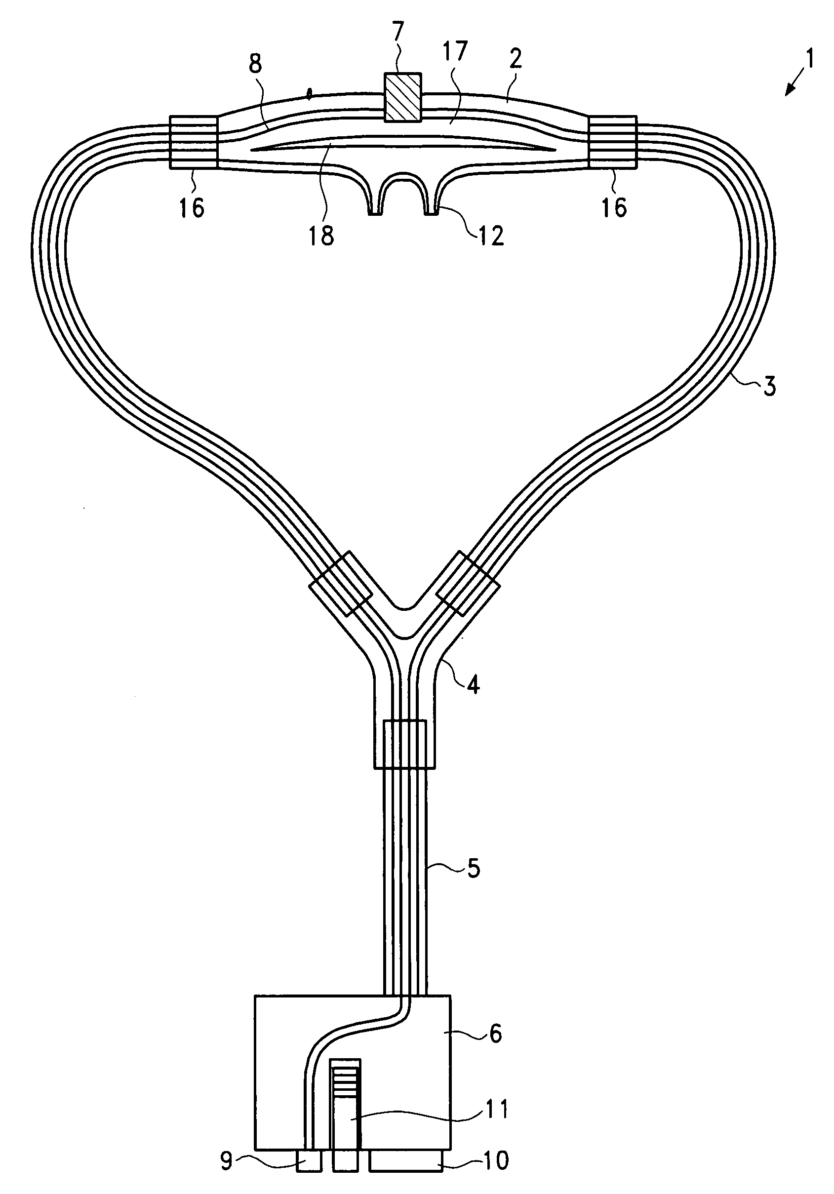
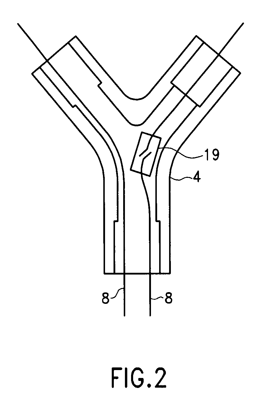
[0035]FIG. 1 shows a nasal cannula 1 according to the invention, comprising a nosepiece 2. The nose piece 2 is supplied with compressed air via a forked tube 3, a Y-shaped element 4, a supply tube 5 and a connector 6. The nosepiece 2 includes two prongs 12 for administrating air into both nostrils of a user. Internal radius steps 16 compensate the difference between the internal and external radius of the forked tubes, thereby preventing abrupt changes to the cross-section of the airways.

[0036] The connector 6 comprises a pneumatic connector part 10, an electrical connector part 9 as well as a clamp 11. From the electrical connector part 9 a heating wire 8 is passed through the supply tube 5, the Y-shaped element 4, the right element of the forked tube 3, the right part of the nosepiece 2 to a temperature sensor 7, and from there through the left part of the nosepiece 2, the left element of the forked tube 3, the Y-shaped element 4 and the supply tube 5 back to the electrical connec...

second embodiment

[0044]FIG. 3 shows a nasal cannula, in which the supply tube 5 and the Y-shaped element 4 have been replaced by a double-lumen tube 13. The double-lumen tube consists of two forked tube elements which are mechanically connected to each other. In this embodiment, the Y-shaped element 4 is not applicable or is integrated in the connector 6 according to another perspective. At the point where the two forked tube elements diverge, no sharp edges are provided, but only wide radii. At this point a clip 14 may be provided, which prevents the double-lumen tube from further splicing apart. The division of an airflow to two forked tube elements may be realized in the connector 6 and is, thus, farther away from the prongs 12 so that the noise emission is lower.

[0045]FIG. 4 shows a possibility to read out a temperature sensor via two heating wires only. In the equivalent circuit diagram shown in FIG. 4, the two heating wires 8 are represented by the two resistors RH. RT represents a two-termina...


PUM


Abstract

The invention relates to a nasal cannula for an anti-snoring apparatus, comprising a forked tube pneumatically connected to apertures, which are embodied and positioned in such a way that air can be administered into the nose of a user via these apertures. The nasal cannula further comprises a heating wire extending in the interior of forked tube in such a way that the heating wire can heat the air supplied through the forked tube. The invention moreover relates to a nosepiece and to a Y-shaped element for nasal cannula including internal radius steps at tube connection points. The invention further relates to a nosepiece and to a Y-shaped element having rounded off transition regions. The invention finally relates to a method for avoiding condensation in nasal cannulas. To this end, the gas is heated as it flows through the tubes of a nasal cannula.

Description

[0001] This application claims priority from PCT application PCT / DE2005 / 002335 having publication number WO 2006 / 072231 entitled Air Glasses, Nosepiece, Y-Shaped Element And Corresponding Method by inventors BAUER, KILZ, and MULLER. This application is a continuation of international application number PCT / DE2005 / 002335 (publication number: WO 2006 / 072231 A2) filed on Dec. 30, 2005 and entitled AIR GLASSES, NOSEPIECE, Y-SHAPED ELEMENT AND CORRESPONDING METHOD and claims the benefit of the above-mentioned international application and the corresponding German national patent application number 10 2005 000 922.0 filed on Jan. 7, 2005 and entitled LUFTBRILLE, NASENSTÜCK, Y-STÜCK SOWIE VERFAHREN the contents of which are expressly incorporated herein by reference.FIELD OF THE INVENTION [0002] The invention relates to wearable respiration devices, more specifically to air glasses apparatus, nasal cannula, nosepiece, Y-shaped element and corresponding method. Specifically, the invention r...

Claims


Application Information

Patent Timeline
Patent Type & Authority Applications(United States)
IPC IPC(8): A61M16/00A61M15/08
CPCA61M16/0666A61M16/0808A61M2205/3372A61M16/1095A61M2205/42A61M16/0833A61M2205/3653
Inventor ULLAKILZ, SILVIOMULLER, INGOBAECKE, MARTINKRAUSE, HEIKO
Owner TNI MEDICAL
Why Eureka
Try Eureka