Charged particle beam apparatus and method for charged particle beam adjustment

Active Publication Date: 2007-12-13
HITACHI HIGH-TECH CORP
View PDF24 Cites 23 Cited by
  • Summary
  • Abstract
  • Description
  • Claims
  • Application Information

AI Technical Summary

Benefits of technology

[0018] According to the first aspect of the present invention described so far, deflection is performed after finding the sensitivity of the alignment deflector and so accurate alignment can be accomplished without depending on the conditions of the

Problems solved by technology

Therefore, it takes a long time for a novice operator to complete the adjustment or the adjustment accuracy produces variations.
In addition, even if the apparatus is used under the same optical conditions, there is the problem that the adjustment accuracy is deteriorated by variation in the state of the apparatus provided that the registered aligner-setting conditions are used.
For these reasons, there is the anxiety

Method used


Image

  • Charged particle beam apparatus and method for charged particle beam adjustment
  • Charged particle beam apparatus and method for charged particle beam adjustment
  • Charged particle beam apparatus and method for charged particle beam adjustment

Examples


embodiment 1

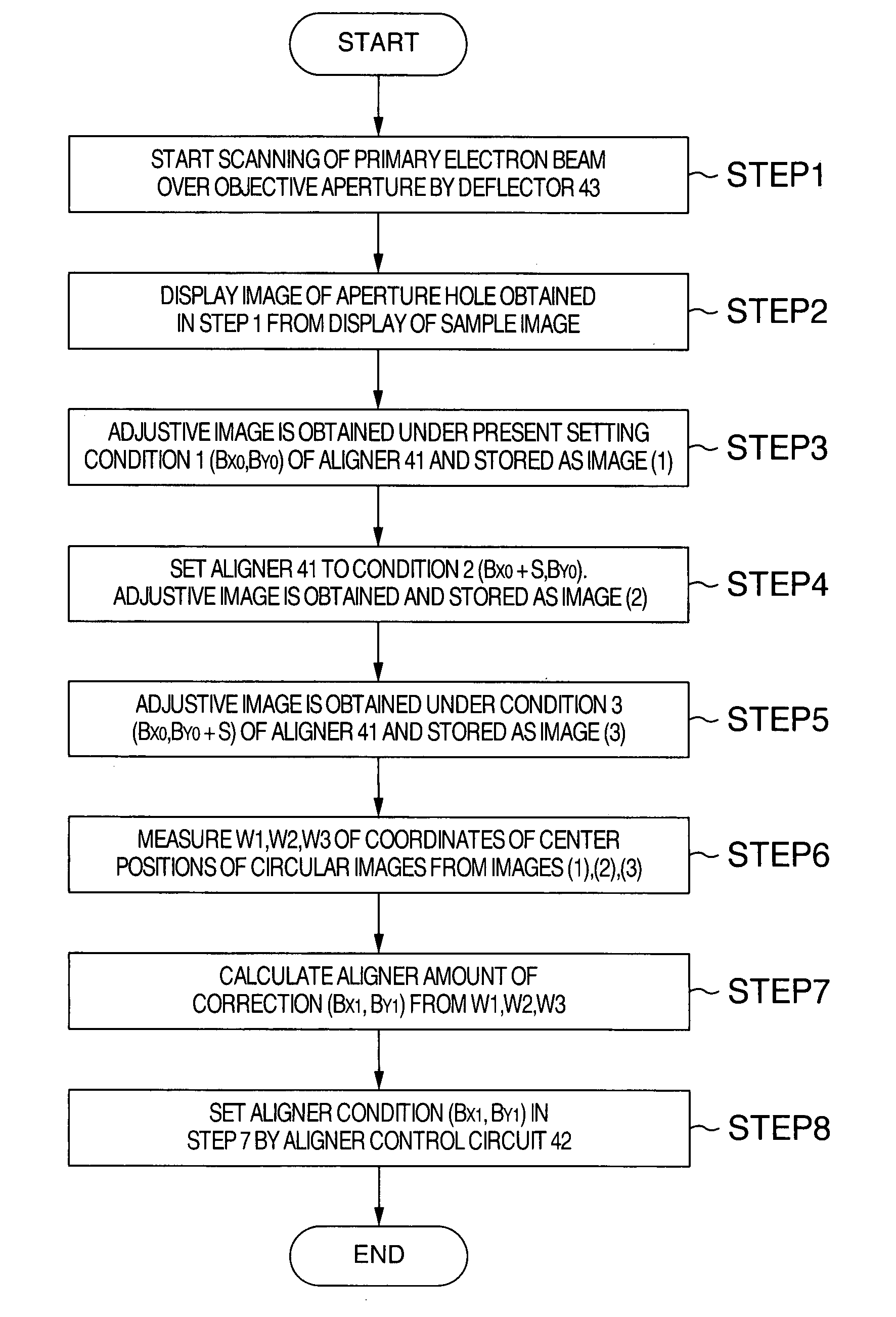
[0036] Measurement of the sensitivity of an aligner performed in the processing step (1) and detection of the deviation between the center of the primary charged particle beam and the center of the objective aperture are described, the detection being performed in the processing step (2).

[0037] The aligner can align the primary charged particle beam normally in X-, and Y-directions (in two dimensions). The initial condition of the aligner is given by (X0, Y0). The amount of correction of the aligner is given by X1, Y1. Where the center position WALB of a circular image on the image used for adjustment of the beam center axis is represented by complex numbers, the relationship given by the following Eq. (1) is obtained.

WALB=C+D·(X1+j·ε·Y1)  (1)

where C is a complex representation of the amount of deviation between the center of the image for adjustment of the beam center axis and the center of the circular image, D is a complex representation of the sensitivity of motion of the ci...

embodiment 2

[0072] The flow of processing of FIG. 10 is described in detail in the following.

[0073] In step 1, the present condition of the objective lens 57 or a condition determined based on the present condition (e.g., a condition slightly shifted in terms of focus from the present focal condition) is set as condition 1 into the objective lens 57. Then, the present condition of the aligner 101 or a previously determined condition is set as condition 1 for the aligner 101. Image 1 is obtained under these objective lens condition 1 and aligner condition 1.

[0074] In step 2, condition 2 of the aligner 101 is obtained as deflection condition for the aligner by deflecting condition 1 by 180° within a plane perpendicular to the optical axis as shown in FIG. 11. This condition 2 is set into the aligner 101. Image 2 is obtained under condition 1 of the objective lens 57.

[0075] In step 3, condition 3 is obtained as deflection condition for the aligner 101 by deflecting condition 1 or 2 of the align...

embodiment 3

[0091] On the other hand, with respect to the astigmatic corrector 102, more accurate automated axial adjustment can be made by the flow of processing as illustrated in FIG. 10 in the present embodiment. The principle on which optimum conditions for astigmatic correction are derived from the obtained parallaxes is described in patent reference 2.


PUM


Abstract

A charged particle beam apparatus facilitating adjusting the beam center axis of a charged particle beam in a case where optical conditions are modified or in a case where the beam center axis of the charged particle beam is moved due to state variation of the apparatus. When the beam center axis of a primary charged particle beam is adjusted with a deflector (aligner), a processing step (1) for measuring the sensitivity of the aligner and a processing step (2) for detecting the deviation between the center of the primary charged particle beam and the center of the objective aperture are provided. The charged particle beam apparatus has means for determining the aligner set values, using the aligner sensitivity measured in the processing step (1) and the amount of deviation detected in the processing step (2), such that the primary charged particle beam passes through the center of the objective aperture and controlling the aligner using the aligner set values.

Description

BACKGROUND OF THE INVENTION [0001] The present invention relates to a charged particle beam apparatus and, more particularly, to a charged particle beam apparatus in which a primary charged particle beam is allowed to easily pass through the center either of an objective aperture or of an aperture present within the orbit in which the charged particle beam passes, whereby the apparatus is adapted to obtain a high-brightness image stably. [0002] In a charged particle beam apparatus typified by a scanning electron microscope, a sharply focused primary charged particle beam is scanned over a sample to obtain information (e.g., an image of the sample) from the sample. The microscope column of such a charged particle beam apparatus has an objective aperture for appropriately limiting the current hitting the sample (probe current). If there is a deviation between the center of the objective aperture and the center of the primary charged particle beam, the amount of the probe current of th...

Claims


Application Information

Patent Timeline
IPC IPC(8): G01N21/00
CPCG01N23/22H01J37/1471H01J37/28H01J2237/1501
Inventor OGASHIWA, TAKESHISATO, MITSUGUTAKANE, ATSUSHIAGEMURA, TOSHIHIDENARITA, YUUSUKESHICHIJI, TAKEHARUTOMITA, SHINICHIITO, SUKEHIROKATANE, JUNICHI
Owner HITACHI HIGH-TECH CORP
Why Eureka
Try Eureka