Magnet for a dynamoelectric machine, dynamoelectric machine and method

a technology of dynamoelectric machines and magnets, applied in the direction of dynamoelectric machines, electrical apparatus, magnetic circuit shapes/forms/construction, etc., can solve the problems of high remanence magnet materials that are more susceptible to unrecoverable demagnetization, the materials required to achieve demagnetization are more expensive than others, and the material required to achieve demagnetization is more expensiv

Inactive Publication Date: 2007-12-13
REMY TECHNOLOGIES LLC
View PDF3 Cites 71 Cited by
  • Summary
  • Abstract
  • Description
  • Claims
  • Application Information

AI Technical Summary

Problems solved by technology

For a given (BH)max, however, magnet materials with high remanence (Br) typically are more susceptible to unrecoverable demagnetization than magnet materials with a low remanence.
Because in a dynamoelectric machine there are electromagnetic fields generated during operation of the machine, and which in some instances subject permanent magnets to reverse polarity fields, unrecoverable demagnetization can be problematic for machine longevity.
While it is possible to obtain both high remanence and coercivity, the materials required to do so are more expensive than materials that have a moderate to low value of either coercivity or remanence.

Method used


Image

  • Magnet for a dynamoelectric machine, dynamoelectric machine and method
  • Magnet for a dynamoelectric machine, dynamoelectric machine and method
  • Magnet for a dynamoelectric machine, dynamoelectric machine and method

Examples


Embodiment Construction

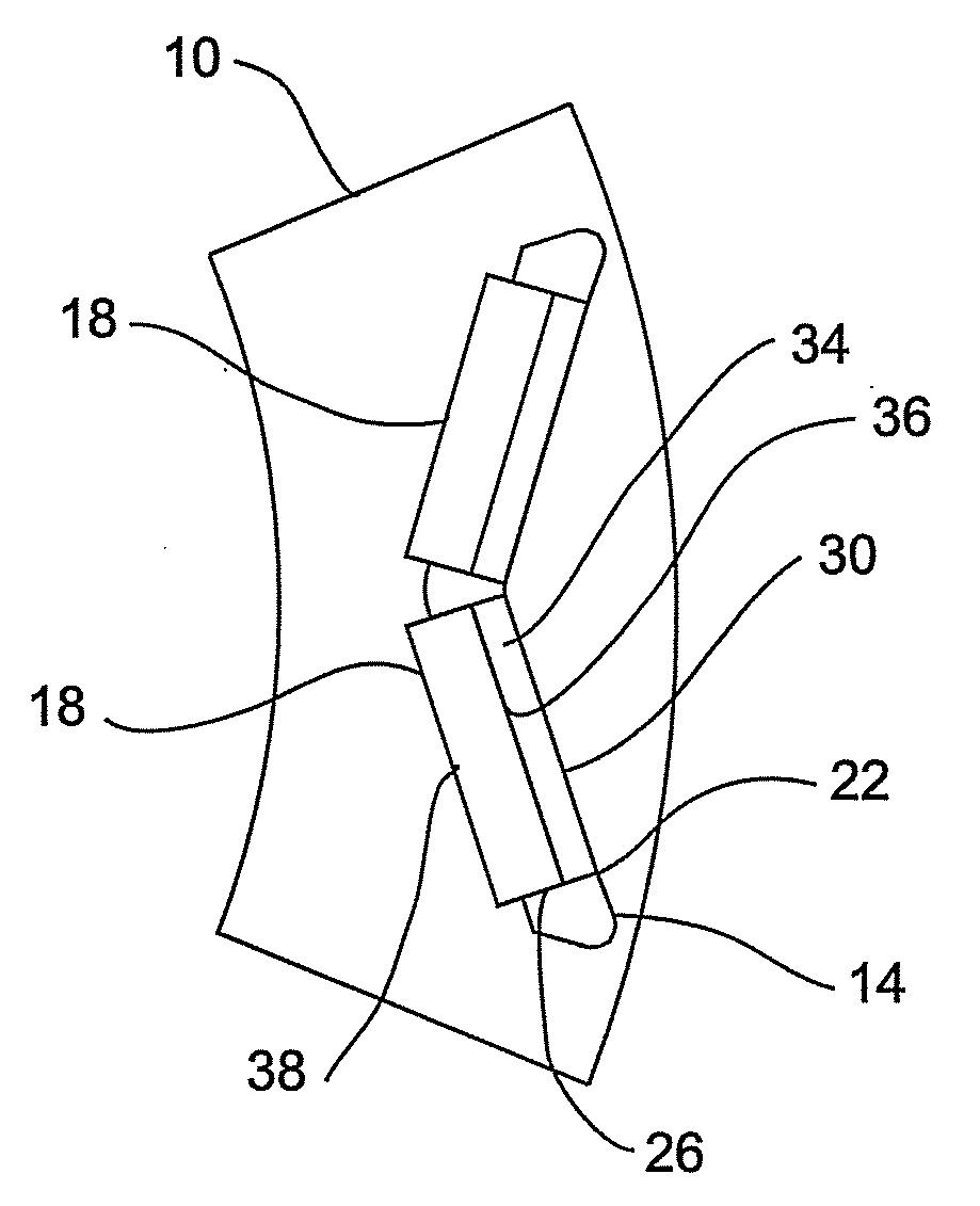
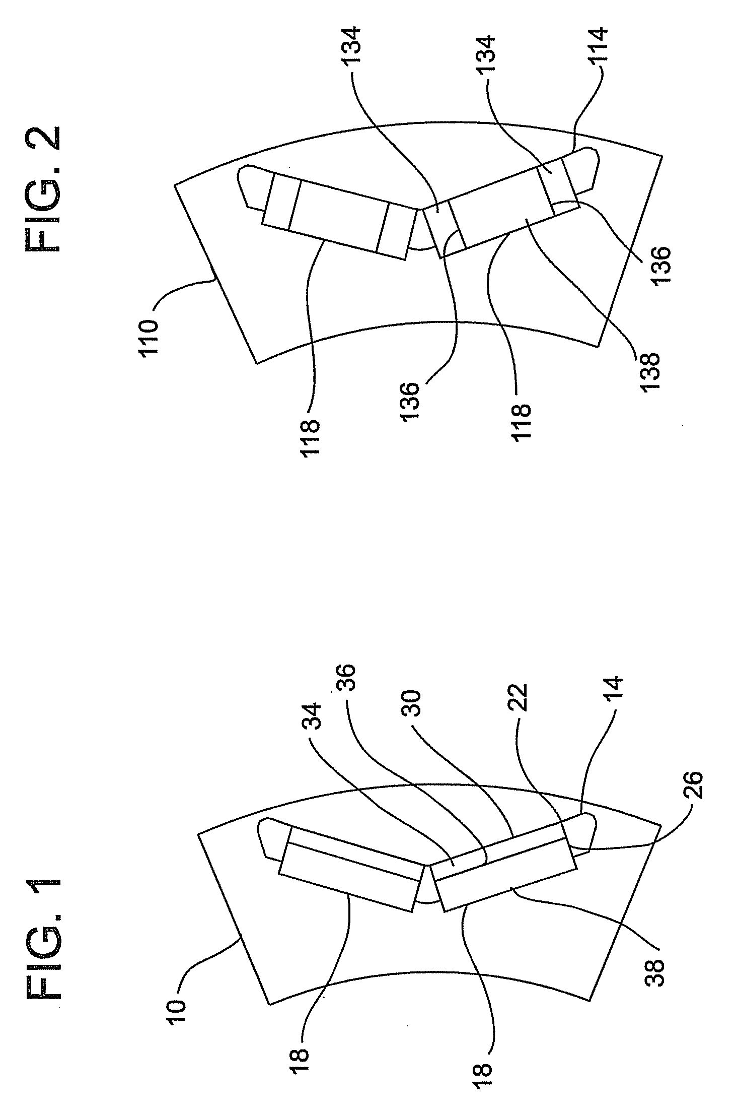
[0016]Referring to FIG. 1 a dynamoelectric machine member 10, of an internal permanent magnet machine, depicted in this exemplary embodiment as a rotor, has a cavity 14 formed therein for locating and positioning magnet members 18. The cavity 14, in one embodiment, is sized to provide a press-fit with the magnet members 18 thereby preventing relative movement between the rotor 10 and the magnet members 18. It is to be appreciated that while machine member 10 and other similar members are illustrated herein as rotors, they may equally exist as stators, motor casings, etc. without departing from the scope of the invention.

[0017]As described above, the magnetic properties of remanence and coercivity are important to the overall performance of the machine. Other factors affecting performance are the shape of magnet members 18 and the position of the magnet members 18 within the machine. In addition to performance, the shape and position of the magnet members 18 also affects their suscep...


PUM


Abstract

Disclosed herein is an apparatus relating to a magnet member for a dynamoelectric machine comprising, a first portion of the magnet member made of a first magnetic material and a second portion of the magnet member made of a second magnetic material. Further disclosed is a method that relates to increasing performance of an electric machine comprising, determining locations of high demagnetization fields at the dynamoelectric machine, and positioning a magnetic member having a first portion having a higher level of coercivity and a second portion having a lower level of coercivity in the machine such that the portion having a higher level of coercivity is more proximate the location of high demagnetization fields than the portion having the lower level of coercivity.

Description

CROSS REFERENCE TO RELATED APPLICATION[0001]The present application claims priority to U.S. Provisional Patent Application Ser. No. 60 / 813,115, filed Jun. 12, 2006, the entire contents of which are specifically incorporated herein by reference.BACKGROUND OF THE INVENTION[0002]Dyanmoelectric machines often use permanent magnets in conversion of mechanical energy to electrical energy and vice versa. Several parameters regarding the permanent magnets are specified to optimize the performance of the machine such as: shape, size, material and positional locations within the dynamoelectric machine.[0003]The material from which a permanent magnet is fabricated is a primary factor in determining flux density. The performance of a permanent magnet is evaluated in engineering applications by using its maximum energy product, which is the product of flux density (B) and magnetic field strength (H), that is, (BH)max. Generally, a permanent magnet with a higher (BH)max improves the performance o...

Claims


Application Information

Patent Timeline
Patent Type & Authority Applications(United States)
IPC IPC(8): H02K21/12
CPCH02K1/2766H02K1/278H02K1/17
Inventor FULTON, DAVIDCAI, WILLIAM
Owner REMY TECHNOLOGIES LLC
Why Eureka
Try Eureka