Delay Ratio Adjusting Circuit, Delayed Pulse Generation Circuit, and Pulse Width Modulation Pulse Signal Generation Device

a delay ratio and ratio adjusting circuit technology, applied in pulse automatic control, pulse manipulation, pulse technique, etc., can solve the problems of insufficient frequency for laser printer practical application, logic circuits become more complex, and difficulty in increasing resolution

Inactive Publication Date: 2007-12-13
IBM CORP
View PDF10 Cites 19 Cited by
  • Summary
  • Abstract
  • Description
  • Claims
  • Application Information

AI Technical Summary

Problems solved by technology

Although this method is a simple method, the number of combinations of various pulse widths is limited during one cycle specified by the base clock frequency, which makes it difficult to increase resolution.
This is insufficient for a frequency required in practical application of laser printers or the like.
Since a counter having more number of digits has to be produced to increase the resolution further, the logic circuits become more complex and the size of the logic circuits on a semiconductor circuit board becomes larger, which prevents the further increase in the frequency.
That is, it is difficult to generate a pulse with a pulse width corresponding to a basic period not greater than a delay time that a delay element has, thus limiting the resolution.
However, in this PWM circuit, an amount of delay cannot be set to a value not greater than an amount of delay (a delay time) that a delay element has, which does not lead to increase of the resolution.

Method used


Image

  • Delay Ratio Adjusting Circuit, Delayed Pulse Generation Circuit, and Pulse Width Modulation Pulse Signal Generation Device
  • Delay Ratio Adjusting Circuit, Delayed Pulse Generation Circuit, and Pulse Width Modulation Pulse Signal Generation Device
  • Delay Ratio Adjusting Circuit, Delayed Pulse Generation Circuit, and Pulse Width Modulation Pulse Signal Generation Device

Examples


Embodiment Construction

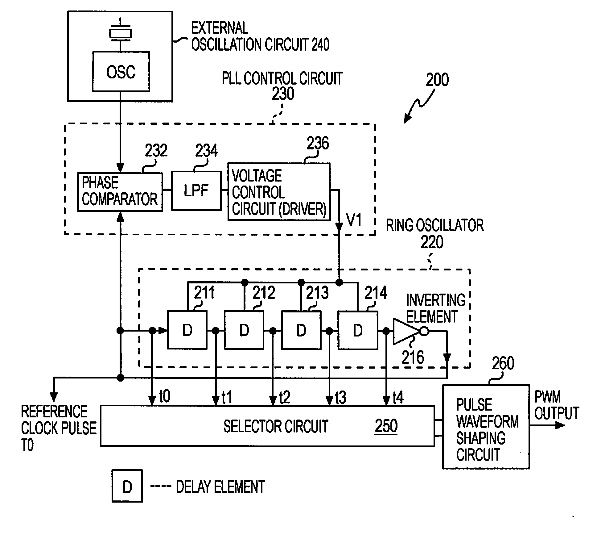
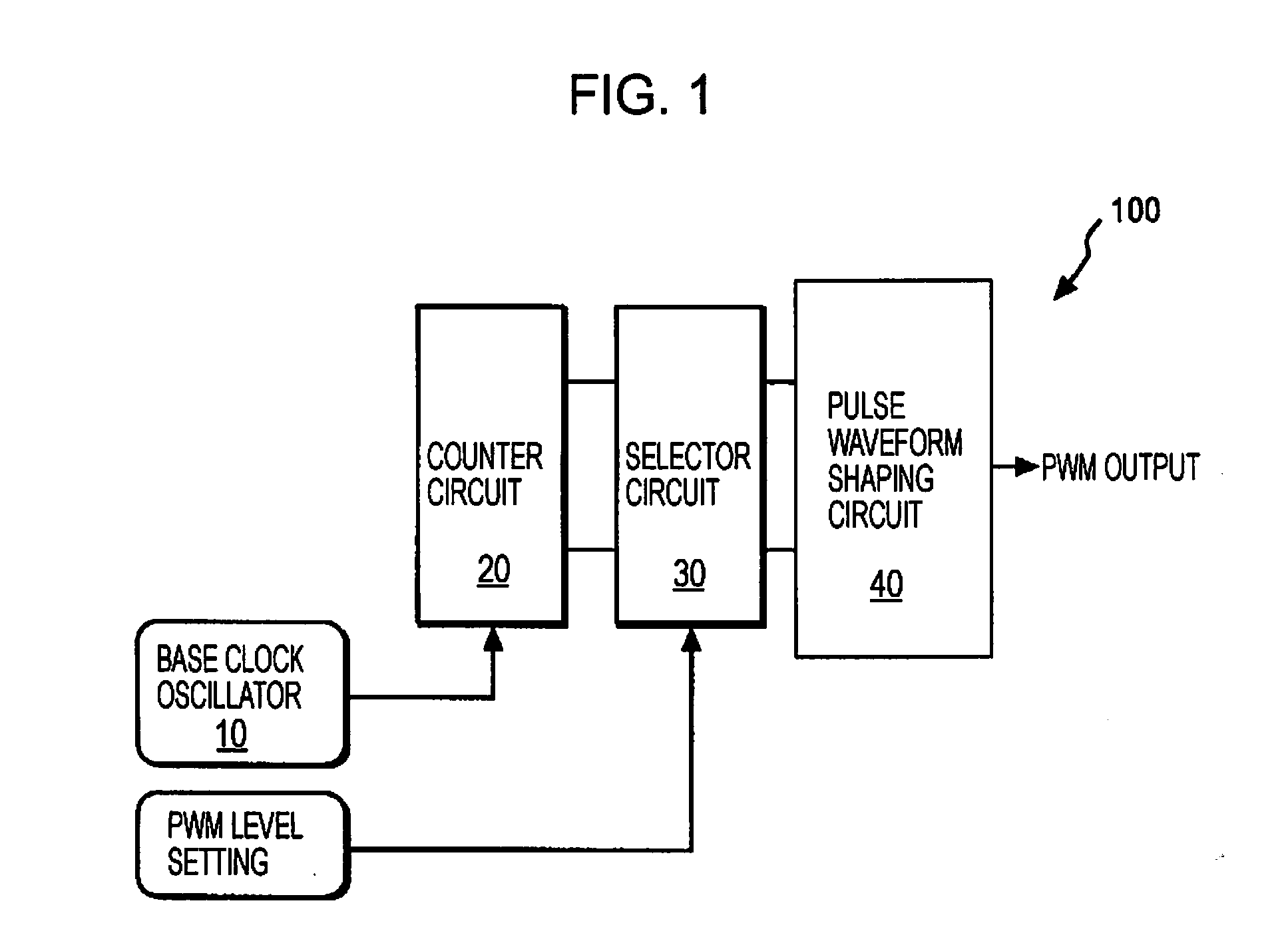
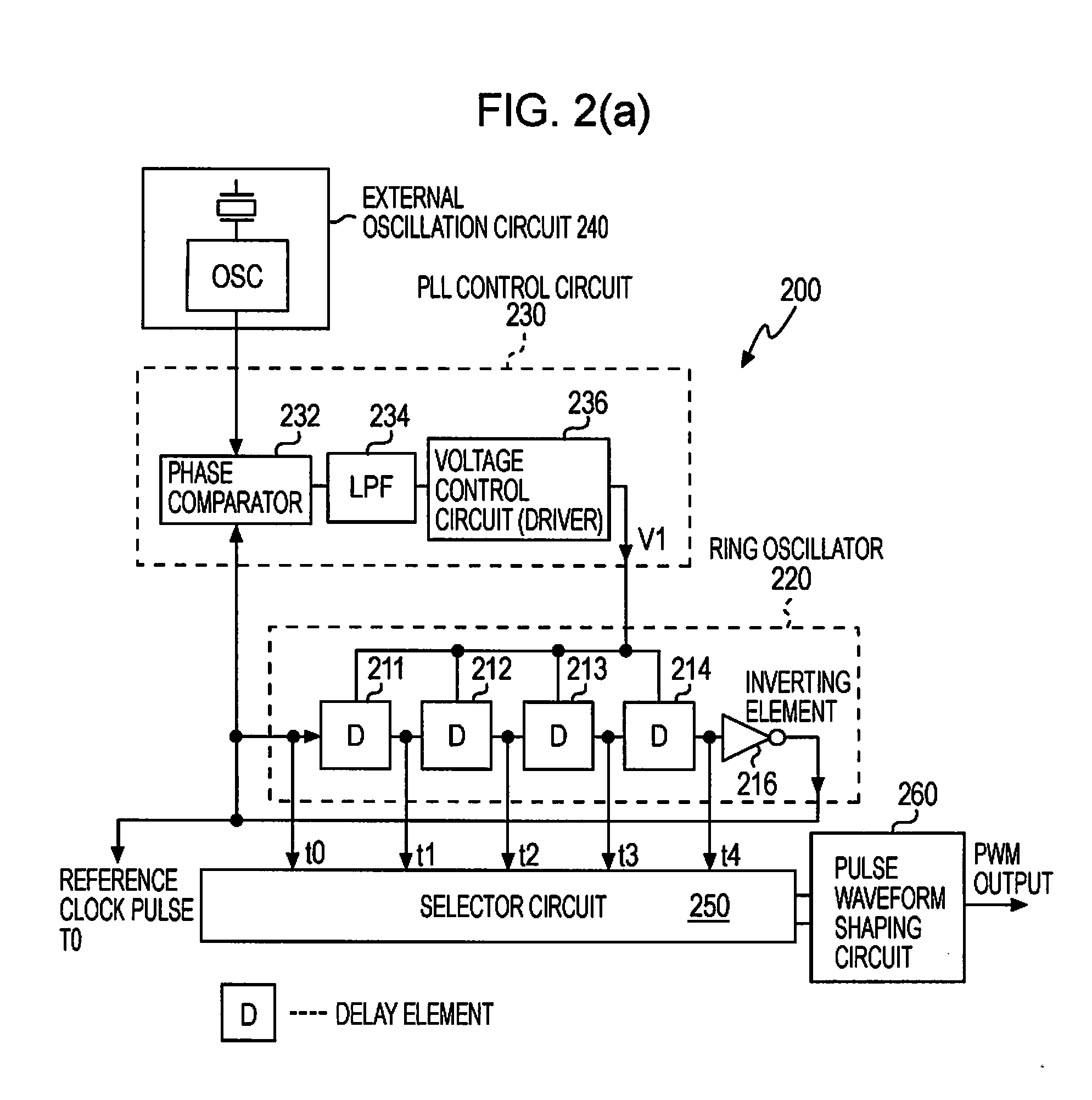
[0021]In an application for laser printers or the like, it is necessary to closely control periods during which light emitting devices, such as laser diodes, are turned on and off during a specified period. Generally, pulse width modulation (PWM) is performed using a ring oscillator having a plurality of delay elements to generate various pulse widths, whereby this control is performed. In this case, the pulse widths cannot be adjusted to a period not greater than a delay time that the delay element has, which restricts increase of accuracy. To solve this problem, an embodiment of the present invention provides a high-resolution-compatible circuit for adjusting a delay time without increasing a base frequency of an external oscillation circuit and to provide a circuit for generating delayed pulsed whose delay times are adjusted.

[0022]Furthermore, another embodiment of the present invention describes a highly accurate and stable pulse width modulation (PWM) pulse signal generation de...


PUM


Abstract

Object To provide a highly accurate and stable pulse width modulation (PWM) pulse signal generation device compatible with high resolution images without increasing a basic frequency of an external oscillation circuit.
Solving Means A PWM pulse signal generation device includes a first PLL control circuit 410, a ring oscillator 420 in which a plurality of basic delay elements are serially connected, and a delayed pulse generation circuit constituted by a delay ratio adjusting circuit 330 and a delay circuit 350. The delay circuit 350 is formed by setting one adjustment delay element having a delay ratio R that is adjusted by the delay ratio adjusting circuit 330 at a first stage and a plurality of serially connecting basic delay elements. An output pulse signal from each delay element of the ring oscillator 420 and an output pulse signal from each delay element of the delay circuit 350 having a delay amount corresponding to the delay ratio are superimposed to perform pulse width modulation, whereby output pulses having various pulse widths can be generated.

Description

FIELD OF THE INVENTION [0001]The present invention relates to devices for supplying pulse-width-modulated pulse output signals, and more specifically, it relates to a high-resolution-compatible PWM (pulse width modulation) pulse signal generation device that operates accurately and stably.BACKGROUND OF THE INVENTION [0002]Accuracy of amount of laser radiation can be improved by closely controlling on / off periods of light emitting devices, such as laser diodes, for use in laser printers or the like. It is possible to improve accuracy of radiation time and amount of radiation as periods, during which the light emitting devices are turned on and off, can be controlled more closely during a predetermined period. More specifically, when the control is performed using pulse width modulation (PWM), the accuracy of radiation time and amount of radiation can be improved as combination of various widths increases.[0003]Generally, a pulse width modulation (PWM) pulse signal is generated in the...

Claims


Application Information

Patent Timeline
Patent Type & Authority Applications(United States)
IPC IPC(8): H03K3/017H03K3/00
CPCH03K7/08H03L7/07H03K5/133H03L7/0812H03L7/0995H03L7/0805
Inventor KUBO, HIROAKI
Owner IBM CORP
Why Eureka
Try Eureka