Broadcast system for electronic ink signs

Inactive Publication Date: 2007-12-13
E INK CORPORATION
View PDF49 Cites 175 Cited by
  • Summary
  • Abstract
  • Description
  • Claims
  • Application Information

AI Technical Summary

Benefits of technology

[0010] An object of the invention is to provide a display system that enables its users to display messages in real time on distributed displays, at a single site or multiple sites, from a central location. The invention features a display comprising an electrically active display, a data receiver which may transmit as w

Problems solved by technology

To date, widespread incorporation of displays has been hindered because such applications generally require flexible displays that consume very little power.
Despite much effort directed to developing highly-flexible, reflective display media, there are relatively few examples of displays formed on semi-flexible substrates, and these examples have found only moderate success.
Nevertheless, problems remain with liquid crystal alignment in TN and STN displays, cholesteric displays are sensitive to changes in their cell gap, and local stress can cause changes in the scattering or absorbance of PDLC and cholesteric films.
As such, only moderate flexibility can be achieved with these displays.
However, these devices require continuous power consumption for operation, and thus are not practical for many applications.
Another problem with developing highly flexible displays is the lack of an appropriate conductor for addressing the display elements.
An ITO layer, however, can be damaged when the display is f

Method used


Image

  • Broadcast system for electronic ink signs
  • Broadcast system for electronic ink signs
  • Broadcast system for electronic ink signs

Examples


Example

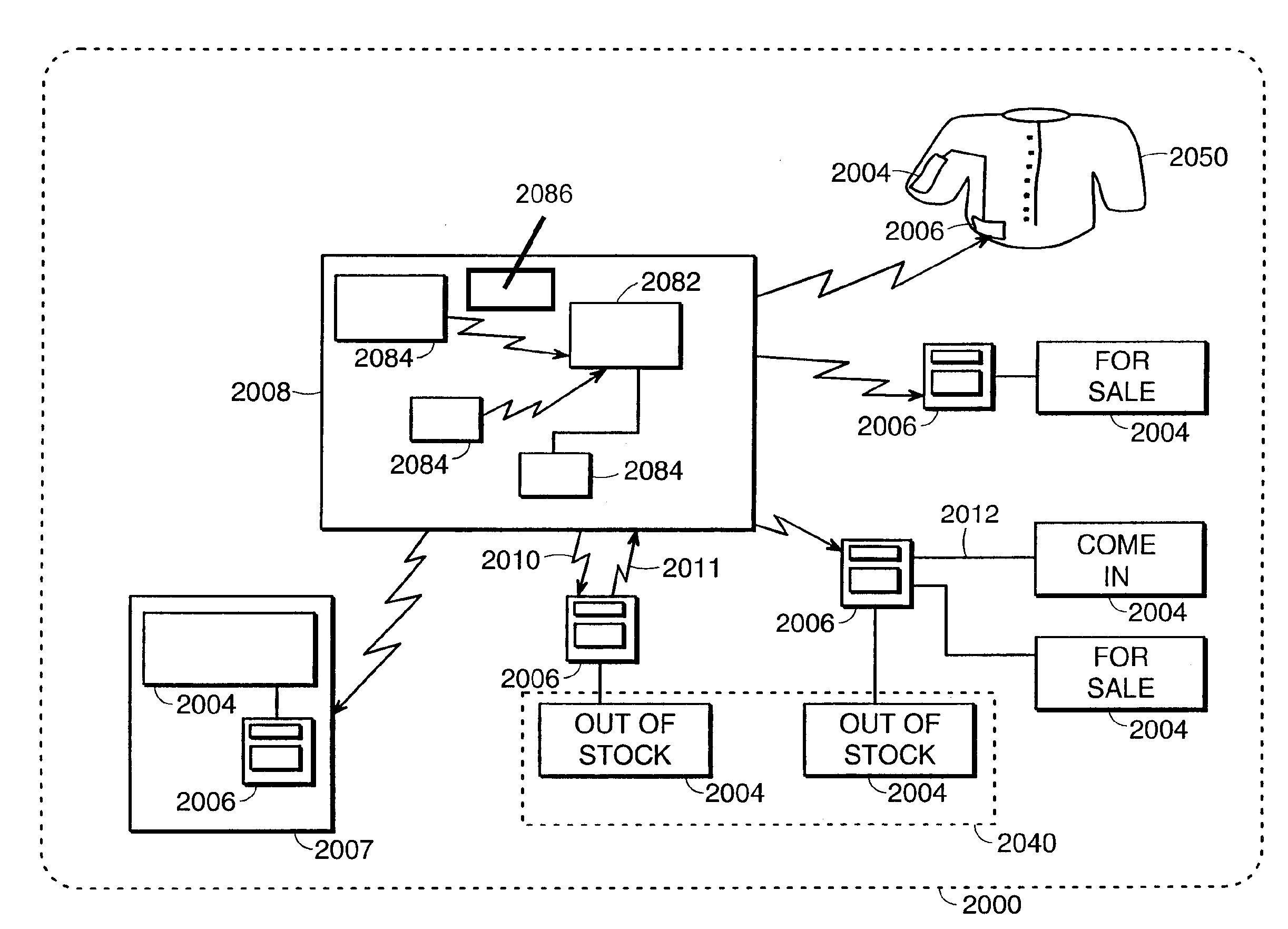
[0039] According to the present invention, a control system is provided which communicates with a data receiver in electrical communication with an electrically active display. The present invention takes advantage of the addressable nature of an electrically active display to centrally control the appearance of the electrically active display.

[0040] In a preferred embodiment, all ongoing aspects of control system operation are handled by a server, as directed by a client. In another embodiment, clients are grouped to form an organization client account. In one detailed embodiment, each organization client account has a separate authorization database and display database.

[0041] In one embodiment, the server validates that a client has sufficient access to enter the control system and determines the authorization level of the client to send a specific-message or perform other functions on the control system. When provided with a new message and a list of electrically active displa...


PUM


Abstract

A system for centrally controlling and messaging electrically active displays distributed at a single site or at multiple sites. A process for creating an electronically addressable display includes multiple printing operations, similar to a multi-color process in conventional screen printing. In some of the process steps, electrically non-active inks are printed onto areas of the receiving substrate, and in other steps, electrically active inks are printed onto different areas of the substrate. The printed display can be used in a variety of applications. This display can be used as an indicator by changing state of the display after a certain time has elapsed, or when a certain pressure, thermal, radiative, moisture, acoustic, inclination, pH, or other threshold is passed. In one embodiment, the display is incorporated into a battery indicator. A sticker display is described. The sticker is adhesive backed and may then be applied to a surface to create a functional information display unit. This invention also features a display that is both powered and controlled using radio frequencies. It describes a complete system for controlling, addressing, and powering a display. The system includes an antenna or antennae, passive charging circuitry, and active control system, a display, and an energy storage unit. There is also a separate transmitter that provides the remote power for the display. The system is meant to be used anywhere it is useful to provide intermittent updates of information such as in a store, on a highway, or in an airport. A tile-based display allowing a modular system for large area display is created using a printable display material.

Description

REFERENCE TO RELATED APPLICATIONS [0001] This application is a continuation of copending application Ser. No. 10 / 730,532, filed Dec. 8, 2003 (Publication No. 2004 / 0119681), which in turn in a continuation of application Ser. No. 09 / 432,343, filed Nov. 2, 1999 (now abandoned), which itself claims benefit of Provisional Patent Application Ser. No. 60 / 106,713, filed Nov. 2, 1998. The entire disclosures of all the aforementioned applications are incorporated herein by reference.FIELD OF THE INVENTION [0002] The present invention relates to display applications, and in particular, to displays that may be updated with data from an external source. BACKGROUND OF INVENTION [0003] Many applications can benefit from inclusion of a display. For example, projection devices, sketching apparatuses, telephones, pocketbooks, and battery indicators are only a few applications that display transient information. To date, widespread incorporation of displays has been hindered because such applications...

Claims


Application Information

Patent Timeline
IPC IPC(8): G09G3/34
CPCG06F3/147G09G3/344G09G2380/06G09G2300/026G09G2380/04G09G3/38
Inventor ALBERT, JONATHAN D.WILCOX, RUSSELL J.GATES, HOLLY
Owner E INK CORPORATION
Why Eureka
Try Eureka