Supercharge Your Innovation With Domain-Expert AI Agents!

Generating annotation graphics in 2D form to model 3D elements

Inactive Publication Date: 2007-12-13
AUTODESK INC
View PDF3 Cites 38 Cited by
  • Summary
  • Abstract
  • Description
  • Claims
  • Application Information

AI Technical Summary

Benefits of technology

[0008]The present invention is directed to methods and computer program products that minimize tedious updating tasks and costly coordination errors by automatically generating an annotation graphic in 2D form to model a 3D element in a CAD system. One embodiment of the invention is a method for generating an annotation graphic in 2D form to model a 3D element. A CAD system automatically generates the annotation graphic of a particular element in 2D form based on both a 3D model of the element and the position of a 2D view plane with respect to the element. The annotation graphic indicates whether the element is below the 2D view plane or rises above the 2D view plane. The method may further include displaying the generated annotation graphic. The annotation graphic may also indicate the service type for the element and / or the direction of flow for the element based on information in an analytical model that is associated with or part of the 3D model. The elements may represent piping elements, ductwork elements, plumbing elements, or any other kind of elements.
[0010]Advantageously, by automatically generating annotation graphics, the CAD system eliminates the time users currently spend manually reformatting and updating all the annotations. This minimizes tedious updating tasks and costly coordination errors.

Problems solved by technology

Manually creating these annotation graphics is a time-consuming and error-prone process.
Much time may be lost reformatting a set of drawings or updating numerous annotations manually.
An engineer or draftsperson typically wastes time performing tedious updating tasks and sometimes makes costly coordination errors.
Conventional CAD systems are unable to automate such tasks due to the lack of native intelligence in the CAD system software regarding the way fluid / air moves through the system and the connections between elements, among other information.

Method used


Image

  • Generating annotation graphics in 2D form to model 3D elements
  • Generating annotation graphics in 2D form to model 3D elements
  • Generating annotation graphics in 2D form to model 3D elements

Examples


Embodiment Construction

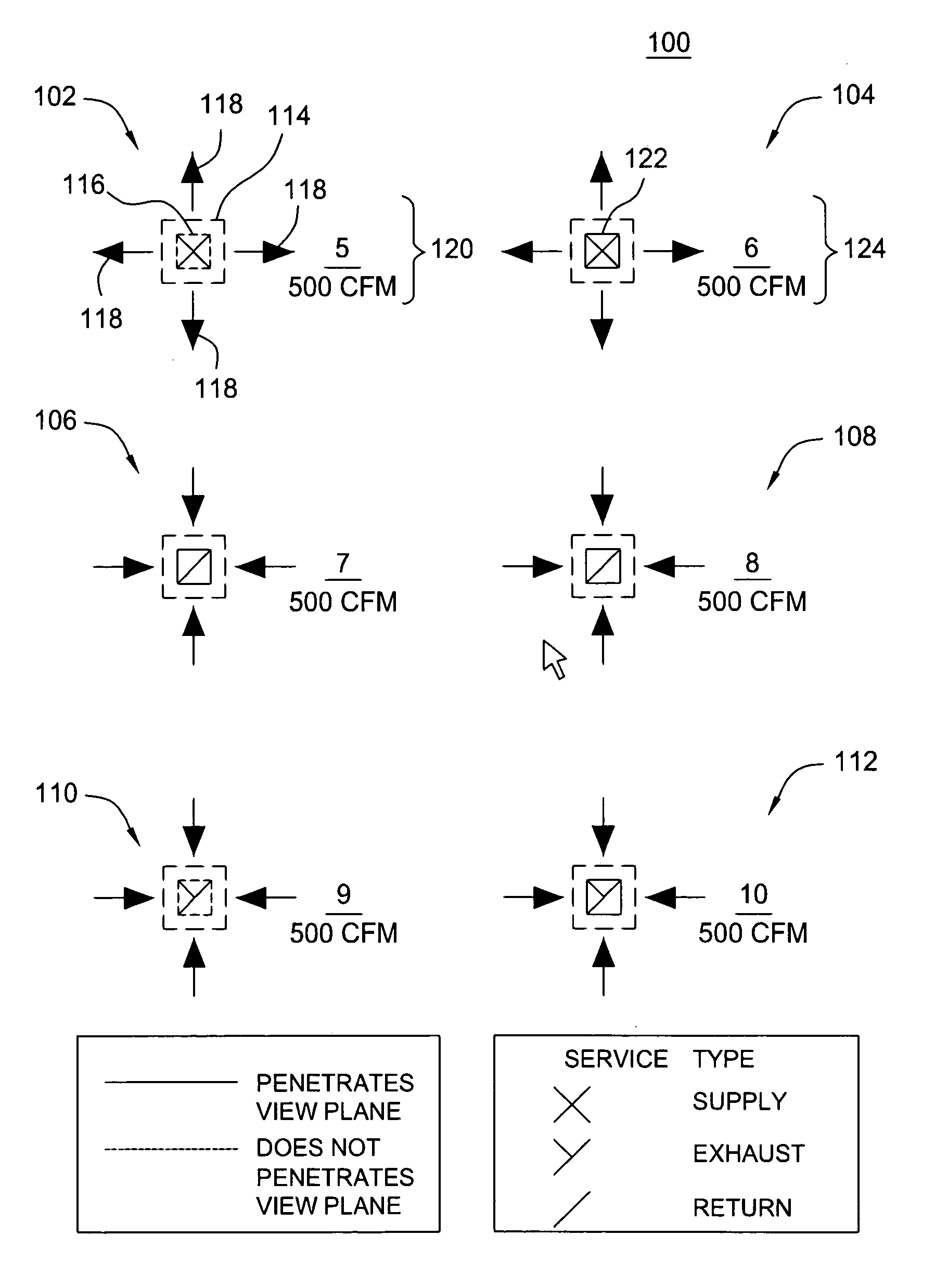
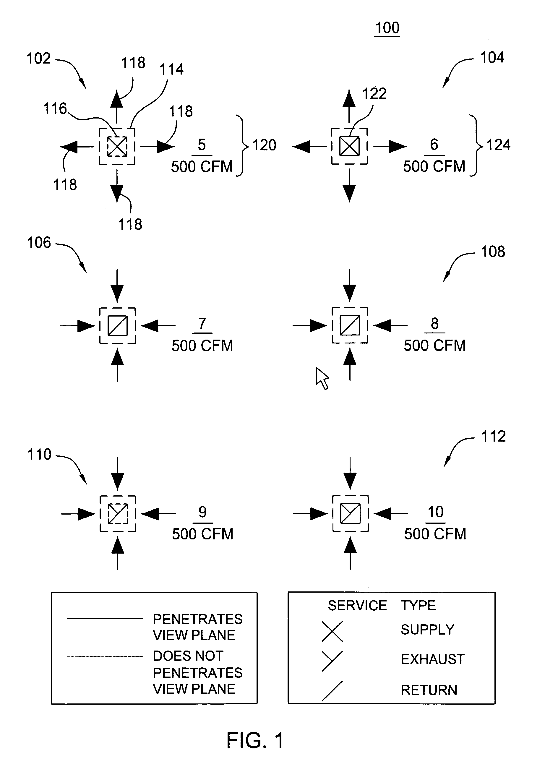
[0022]One exemplary embodiment is a CAD system that generates an annotation graphic in 2D form to model a 3D element. The CAD system couples intelligent 3D model elements with an analytical model that describes, for example, fluid / air flow through the 3D model. The CAD system automatically generates annotation graphics based on information associated with the models, such as the service that the elements provide and the relationship between the elevation of the elements and the 2D view plane. However, embodiments of the invention are not limited to any particular kind of CAD system, 3D models, analytical models, service, or graphical symbols. Although the detailed description includes graphical representations for piping elements, ductwork elements, and plumbing elements, the present invention applies to representations of virtually any real-world construct, such as electrical, mechanical, architectural, or structural elements, or and other kind of design or construction elements fo...


PUM


Abstract

A model-based design system couples intelligent 3D model elements with an analytical model that describes fluid flow through the 3D model. The system automatically generates annotation graphics for a 2D view of the elements with respect to a view plane. The system displays a drop symbol when the elements are below the view plane and the system displays a rise symbol when the elements penetrate and rise above the view plane. In addition to the rise / drop indications, the annotation graphics may indicate the type of service provided by the elements and the location and direction of flow. Advantageously, the system generates these annotation graphics automatically from 3D model and the analytical model.

Description

BACKGROUND OF THE INVENTION[0001]1. Field of the Invention[0002]The present invention generally relates to computer graphics and applications, graphical user interfaces, and computer simulation and modeling. More specifically, the present invention relates to a computer-aided design (CAD) system for generating annotation graphics in two-dimensional (2D) form that model three-dimensional (3D) elements.[0003]2. Description of the Related Art[0004]The term computer-aided design (CAD) generally refers to a broad variety of computer-based design tools used by architects, engineers, and other construction and design professionals. CAD systems allow users to create, manage, and share design data with integrated design and data management tools. Some CAD systems allow users to construct 3D models representing virtually any real-world construct, such as homes, offices, and other buildings. These CAD systems typically generate a variety of 2D and 3D views on a computer display, such as plan, ...

Claims


Application Information

Patent Timeline
IPC IPC(8): G06T15/20
CPCG06T2219/004G06T19/00
Inventor CHENG, XINSHENGDESSUREAULT, PAUL FREDMARTIN, JASON
Owner AUTODESK INC
Features
  • R&D
  • Intellectual Property
  • Life Sciences
  • Materials
  • Tech Scout
  • Unparalleled Data Quality
  • Higher Quality Content
  • 60% Fewer Hallucinations
Learn More