Transimpedance (TIA) circuit usable for burst mode communications

a technology of tia circuit and transmission mode, which is applied in the direction of electromagnetic receiver, electrical apparatus, electromagnetic transmission, etc., can solve the problems of optical receiver b, power burst, slow decay,

Inactive Publication Date: 2007-12-13
AVAGO TECH WIRELESS IP SINGAPORE PTE
View PDF11 Cites 22 Cited by
  • Summary
  • Abstract
  • Description
  • Claims
  • Application Information

AI Technical Summary

Problems solved by technology

Also, the high power burst can raise the average power level of a successive low power burst, which decays slowly over time.
Since the data is transmitted in bursts, a problem arises in that the optical receiver 200 must receive and distinguish bur

Method used


Image

  • Transimpedance (TIA) circuit usable for burst mode communications
  • Transimpedance (TIA) circuit usable for burst mode communications
  • Transimpedance (TIA) circuit usable for burst mode communications

Examples


Embodiment Construction

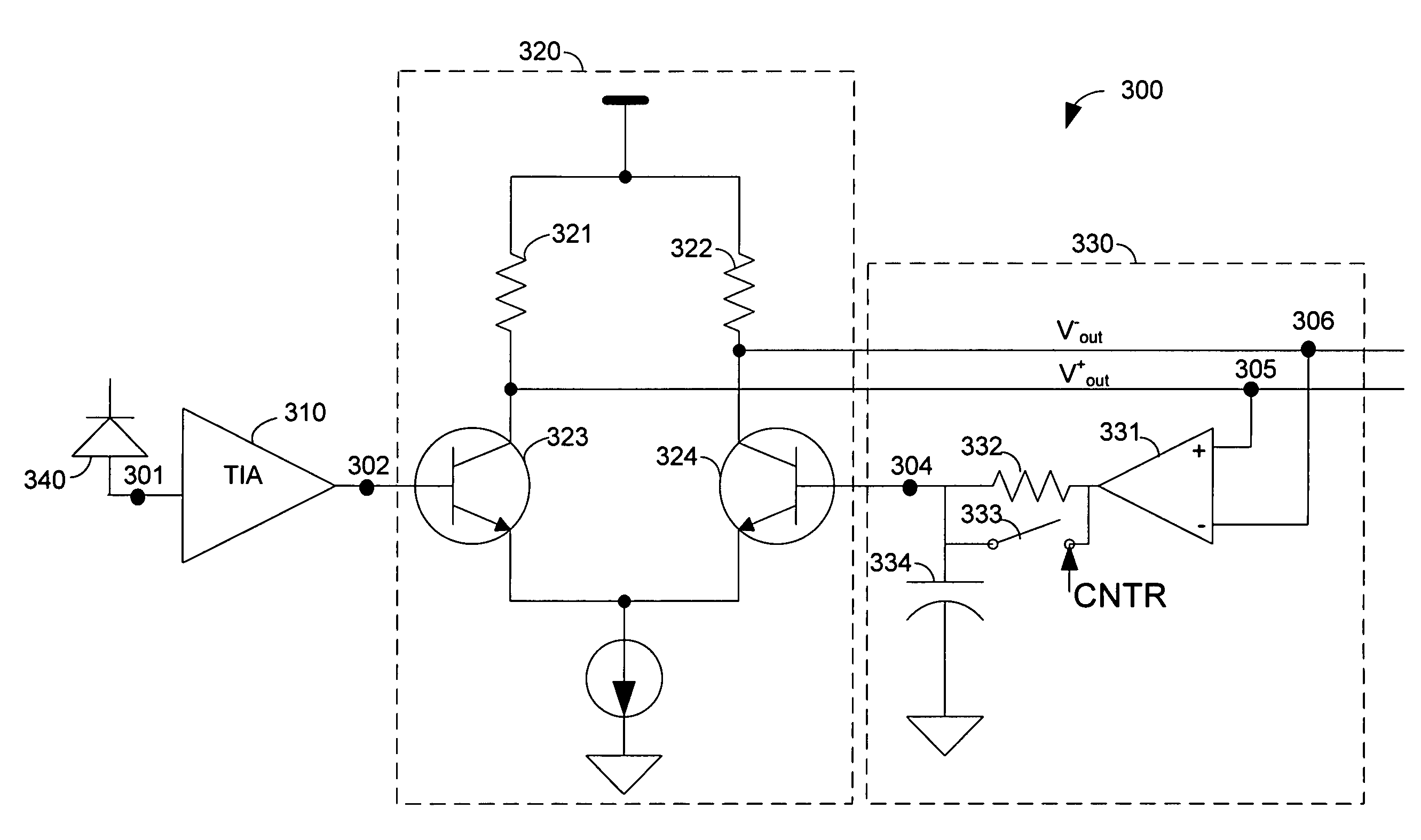
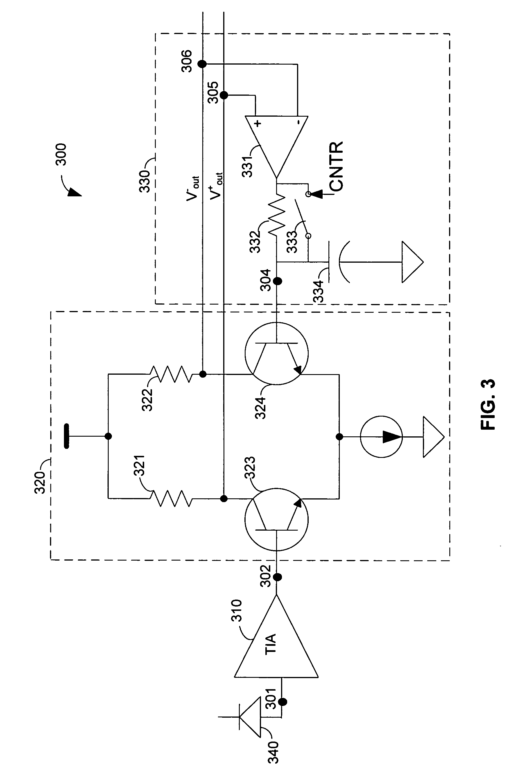
[0031]The present invention provides a TIA circuit usable for burst mode communications. The TIA circuit includes a TIA stage, a limiter-amplifier, and a direct current (DC) restoration loop. The invention overcomes known problems relating to burst communications, such as a DC level in the output signal which can change from burst to burst, and a duty-cycle distortion in large signals. The present invention solves these problems by using a DC restoration loop that ensures achieving substantially zero DC potential within variable acquisition periods.

[0032]FIG. 3 shows a non-limiting schematic diagram of a burst-mode TIA circuit 300 disclosed in accordance with an embodiment of the present invention. Biasing and other accompanying circuitry are not shown, merely for keeping the description simple and without limiting the scope of the disclosed invention. The TIA circuit 300 includes a TIA stage 310, a limiter-amplifier 320, and a DC restoration loop 330. The burst-mode TIA circuit 300...


PUM


Abstract

A transimpedance amplifier (TIA) circuit usable for burst mode communications is provided. The TIA circuit includes a TIA stage, a limiter-amplifier, and a DC restoration loop. The invention overcomes problems of the prior art relating to burst communications, such as a DC level in the output signal which can change from burst to burst and a duty-cycle distortion in large signals. This is achieved by using a DC restoration loop that ensures achieving zero DC potential within variable acquisition periods.

Description

FIELD OF THE INVENTION[0001]The present invention generally relates to transimpedance amplifiers (TIA) circuits, and in particular to burst mode TIA circuits of optical receivers.REFERENCES CITED[0002]Patents and ApplicationsU.S. Pat. No. 6,552,605April 2003YoonU.S. Pat. No. 6,720,827April 2004YoonU.S. Pat. No. 6,876,259April 2005VisocchiU.S. Pat. No. 6,686,799February 2004IvryBACKGROUND OF THE INVENTION[0003]In the related art, most optical receivers and optical communications involve continuous mode communication. One new method for optical communication involves burst mode communication. Burst mode communication is useful, for example, in point to multipoint communication, such as occurs when a single operator is linked to many users. In such operation mode, many users are connected to a single operator using fiber optic lines that are split between the users. In order to prevent interference between the users, every user performs the transmission using a different carrier. Thus,...

Claims


Application Information

Patent Timeline
IPC IPC(8): H04B10/06
CPCH04B10/693
Inventor WEBER, RAVIVLEVY, MOSHEDVIR, RAFI
Owner AVAGO TECH WIRELESS IP SINGAPORE PTE
Why Eureka
Try Eureka