System and method for automatically correcting duty cycle distortion

a technology of automatic correction and duty cycle, applied in the direction of digital transmission, pulse automatic control, transmission, etc., can solve the problems of duty cycle distortion in an optical driver or receiver circuit, common problem in many optical driver and receiver circuits,

Inactive Publication Date: 2007-11-06
SEMTECH CANADA
View PDF34 Cites 17 Cited by
  • Summary
  • Abstract
  • Description
  • Claims
  • Application Information

AI Technical Summary

Problems solved by technology

Duty cycle distortion is a common problem in many optical driver and receiver circuits, as well as in other types of circuits.
Duty cycle distortion in an optical driver or receiver circuit may, for instance, be the result of asymmetrical rise and fall times in a typical optical data signal.

Method used


Image

  • System and method for automatically correcting duty cycle distortion
  • System and method for automatically correcting duty cycle distortion
  • System and method for automatically correcting duty cycle distortion

Examples


Embodiment Construction

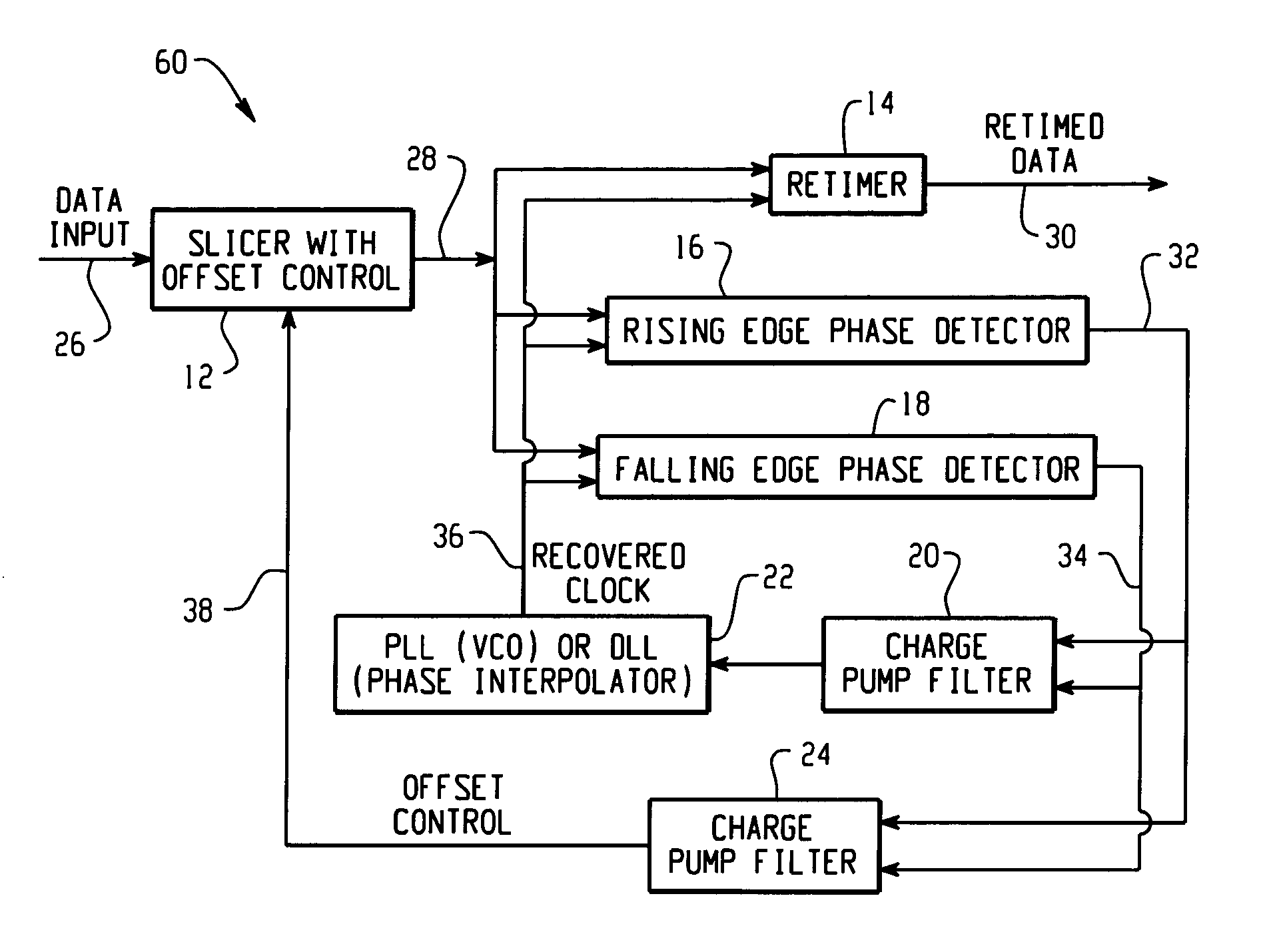
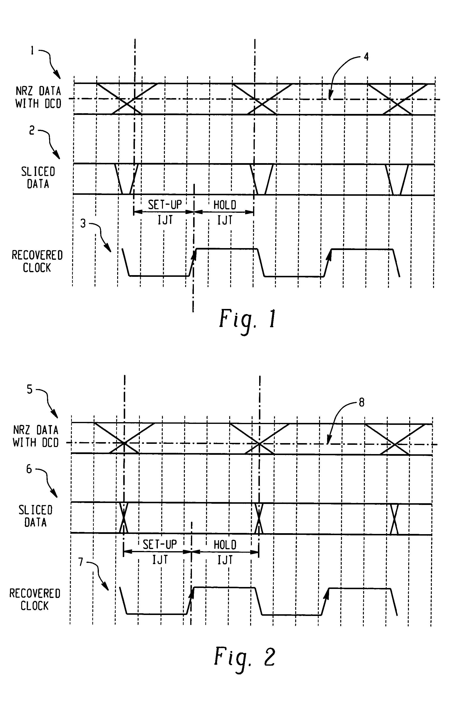
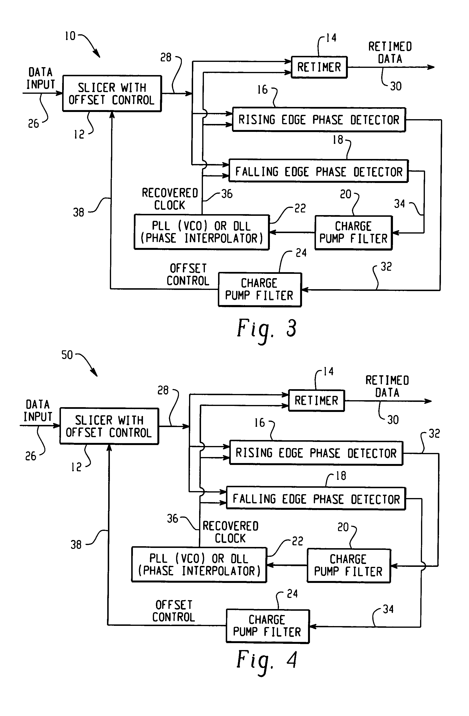
[0012]With reference now to the drawing figures, FIGS. 1 and 2 are timing diagrams illustrating a method for correcting duty cycle distortion in a clock and data recovery system. FIGS. 1 and 2 both illustrate an eye pattern for a typical data input signal 1, 5 received by a clock and data recovery system. Also shown are a sliced data input signal 2, 6 and a recovered clock signal 3, 7. In a typical clock and data recovery circuit, a slicer (e.g., a limiting amplifier) may be used to horizontally slice the data input signal 1, 5 at a pre-selected slicer offset voltage 4, 8. A recovered clock signal 3, 7 is then typically aligned in order to sample the resulting sliced data signal 2, 6. (See, e.g., FIG. 3-5)

[0013]FIG. 1 illustrates a typical default setting for the slicer offset voltage 4. For example, in the case of a differential AC coupled data input signal 1, the default slicer offset voltage 4 will typically be at a zero potential. However, as a result of duty cycle distortion in...


PUM


Abstract

In accordance with the teachings described herein, systems and methods are provided for automatically correcting duty cycle distortion. A slicer may be used to receive a data input signal and compare the data input signal with a slicer offset voltage to generate a sliced data signal. The slicer may also receive an offset control signal to automatically adjust the slicer offset voltage. A phase detector may be used to receive the sliced data signal and a recovered clock signal and to compare the sliced data signal with the recovered clock signal to generate a rising edge output signal and a falling edge output signal. The rising edge output signal may correspond to a phase difference between a rising edge of the sliced data signal and an edge of the recovered clock signal. The falling edge output signal may correspond to a phase difference between a falling edge of the sliced data signal and an edge of the recovered clock signal. A first feedback circuit may be used to phase-lock the recovered clock signal to the sliced data signal utilizing at least one of the rising edge output signal and the falling edge output signal. At least one of the rising edge output signal and the falling edge output signal may be configured in a second feedback circuit to generate the offset control signal.

Description

FIELD[0001]The technology described in this patent document relates generally to circuits for correcting duty cycle distortion in a signal. More particularly, the patent document describes a system and method for automatically correcting duty cycle distortion that is particularly well-suited for use in high-speed, high-performance clock and data recovery circuits.BACKGROUND AND SUMMARY[0002]Duty cycle distortion is a common problem in many optical driver and receiver circuits, as well as in other types of circuits. Duty cycle distortion in an optical driver or receiver circuit may, for instance, be the result of asymmetrical rise and fall times in a typical optical data signal.[0003]In accordance with the teachings described herein, systems and methods are provided for automatically correcting duty cycle distortion. A slicer may be used to receive a data input signal and compare the data input signal with a slicer offset voltage to generate a sliced data signal. The slicer may also ...

Claims


Application Information

Patent Timeline
Patent Type & Authority Patents(United States)
IPC IPC(8): H04L7/00H04L25/00H04L25/40H03L7/081H03L7/087H03L7/089H03L7/091H03L7/099H04L7/033
CPCH03L7/0812H03L7/087H04L7/033H03L7/091H03L7/0891H03L7/0998
Inventor GUPTA, ATUL K.D'HAENE, WESLEY C.
Owner SEMTECH CANADA
Why Eureka
Try Eureka