Electrical card connector

a technology of electrical connectors and cards, applied in the direction of coupling parts, coupling device connections, instruments, etc., can solve the problems of reducing the conductivity of the detecting device, reducing the wear damage of the corresponding switch thereof, and reducing the wear damage of the corresponding switch

Inactive Publication Date: 2007-12-13
HON HAI PRECISION IND CO LTD
View PDF5 Cites 3 Cited by
  • Summary
  • Abstract
  • Description
  • Claims
  • Application Information

AI Technical Summary

Benefits of technology

[0009]An object of the present invention is to provide a card connector in which wear damage of corresponding switch thereof due to insertion or ejection movement of IC cards can be reduced.

Problems solved by technology

However, because the first piece meets with the second piece simply to connect each other, dust and other matter residing on both of communication portions thereof cannot be cleared automatically so that the connecting performance is not reliable.
Furthermore, when the IC card is detected or inserted manually frequently, fingers of users' are easy to touch the first and second contacting portions of corresponding pieces thereby reducing conductivity of the detecting device or damaging the detecting device.

Method used


Image

  • Electrical card connector
  • Electrical card connector
  • Electrical card connector

Examples


Embodiment Construction

[0015]Reference will now be made to the drawing figures to describe the preferred embodiment of the present invention in detail.

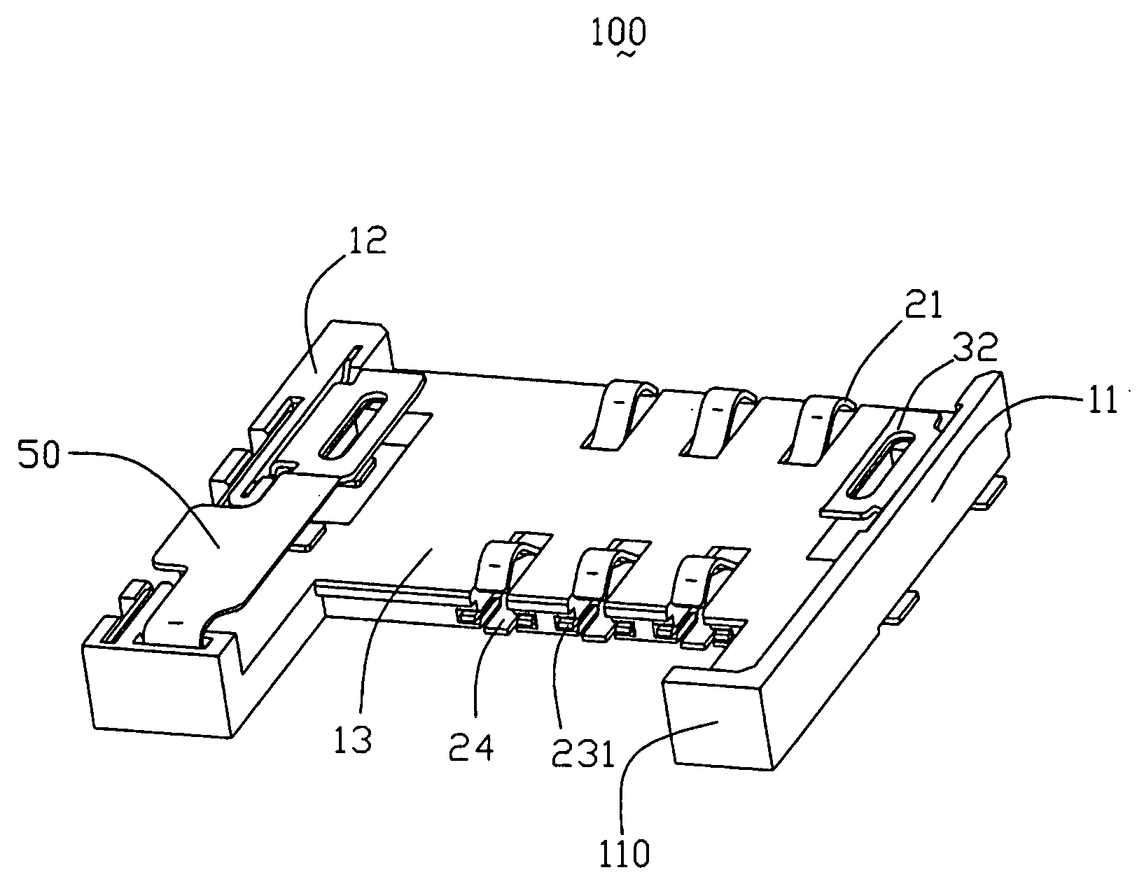
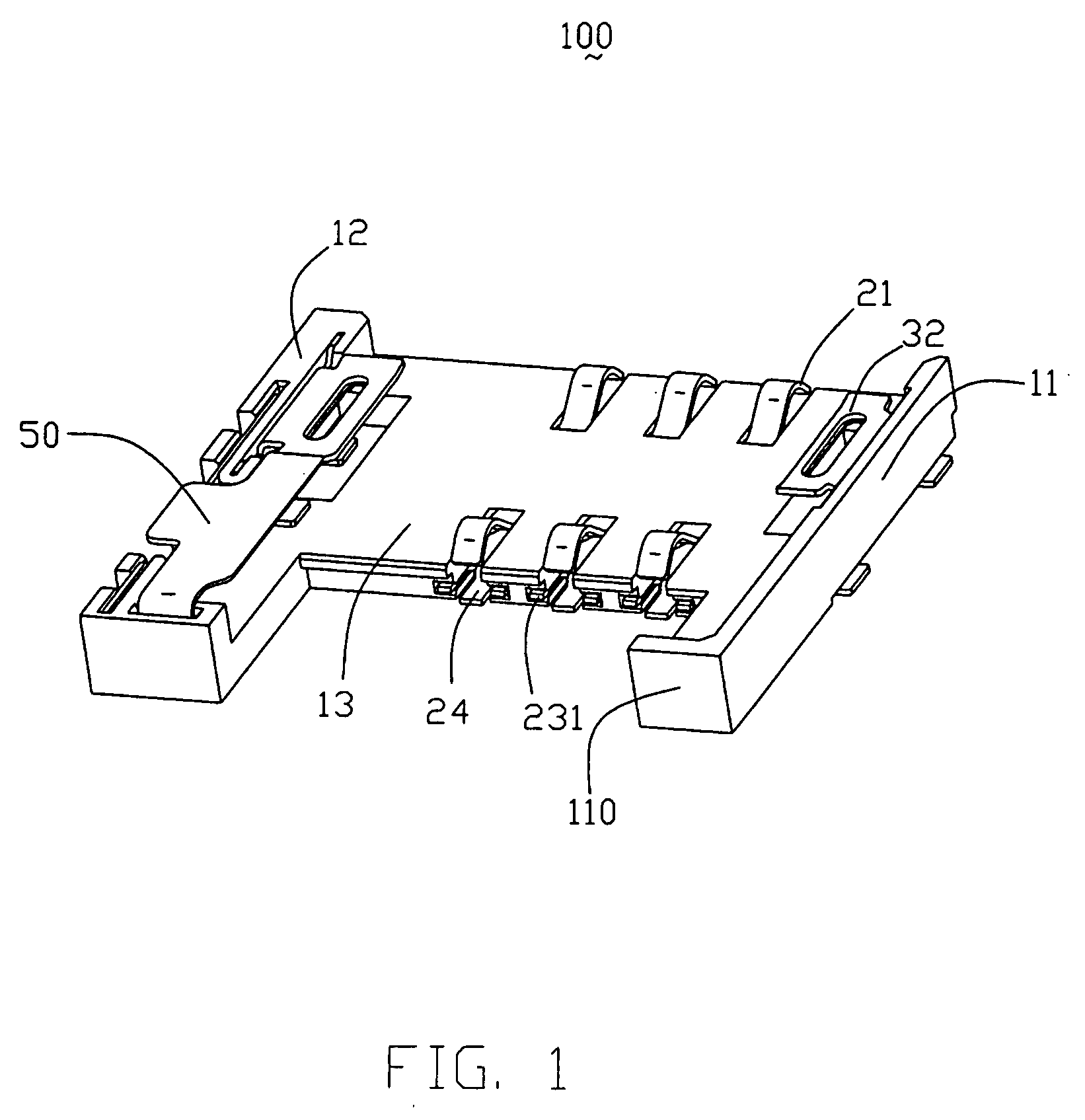
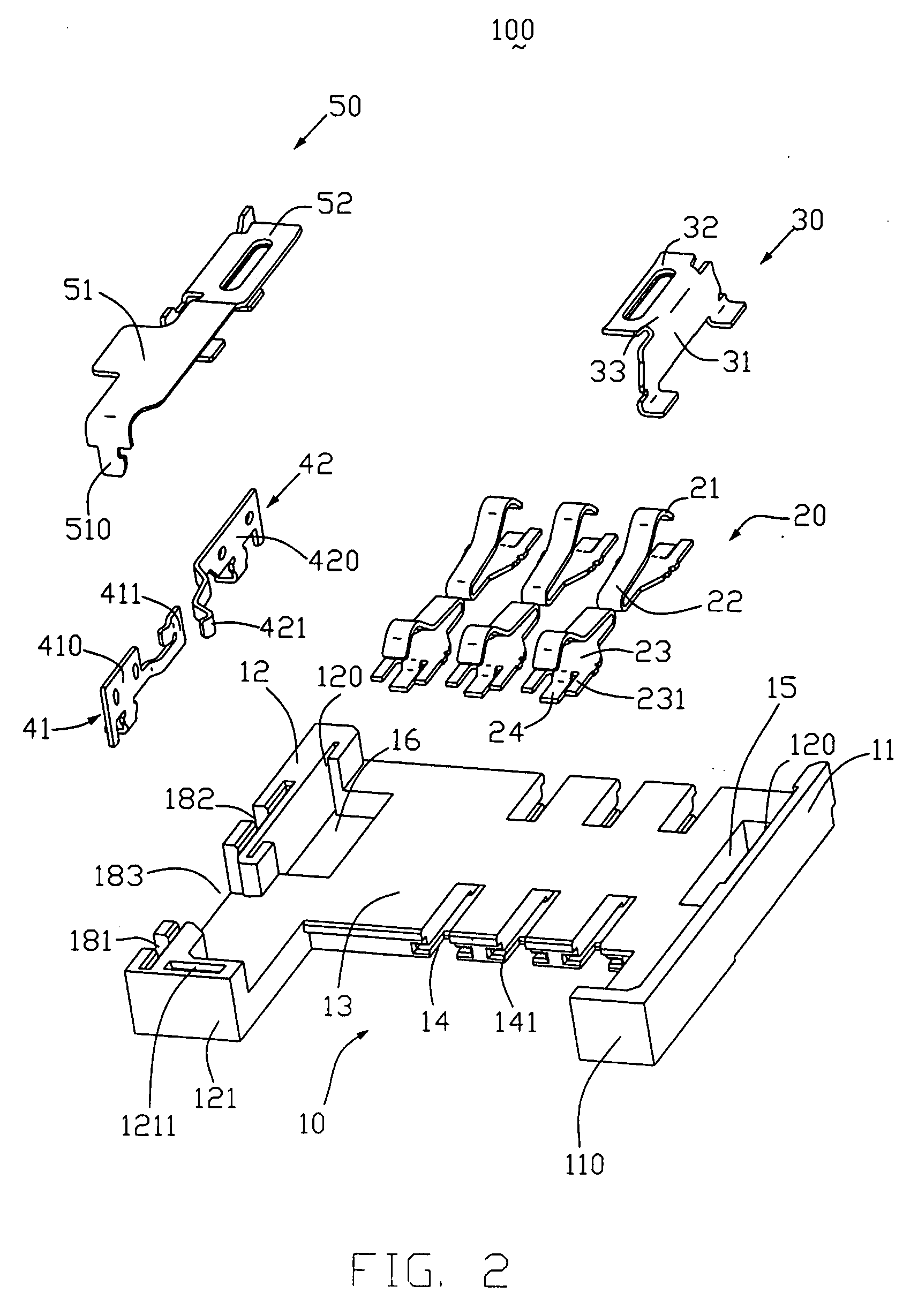
[0016]Referring to FIGS. 1 and 2, a card connector 100 for connecting a card (not shown) to a circuit board (not shown) in accordance with the preferred embodiment of the present invention comprises an insulative housing 10, a plurality of terminals 20 received in the housing 10, a detecting device (not labeled) received in a front portion of the housing 10, a hook 30 engaged with one end of the housing 10, and a cover 50 engaged with opposite end of the housing 10 for covering on top of the detecting device.

[0017]The housing 10 defines a main body 13, a first sidewall 11 and a second sidewall 12 extending from two opposite sides of the main body 13, which together define an upward receiving cavity (not labeled), for receiving the card therein. The main body 13 defines a plurality of passageways 14 for receiving the corresponding terminals 20 therein. Each ...


PUM


Abstract

An electrical card connector (1) includes a housing (10) having a main body (13), and first and second sidewalls (11,12) substantially parallel extending forwards form opposite ends of the main body; the main body defining a receiving cavity together with the first and second sidewalls for receiving an electrical card, a plurality of terminals (20) disposed in the housing and each having a connect portion (21) extending into the receiving cavity for contacting the card, and a pair of switching terminals (41, 42) engaged with the housing and each defining a contacting portion to connect with each other, and a cover (50) engaged with the housing and covering onto the contacting portions of the switching terminals.

Description

BACKGROUND OF THE INVENTION[0001]1. Field of the invention[0002]The present invention relates to electrical connectors, especially to a card connector provided for electrically connecting a card to a circuit board.[0003]2. Description of Related Art[0004]In electronic appliances, such as portable telephones, PDA, digital cameras and the like, addition of a variety of functions and identification of a user are achieved by inserting an IC card with a built-in IC, such as a SIM (subscriber identify module) card, an MMC (multimedia card), an SD (secure digital or super density) card, an MS (memory stick) card and the like therein. Such an IC card is usually connected to the circuit board via a card connector.[0005]The IC card of this kind normally has some means for inhibiting the write operation in order to protect information stored in its internal memory. A means is also provided to cancel the write protection to allow information to be written from an electronic device into the memo...

Claims


Application Information

Patent Timeline
Patent Type & Authority Applications(United States)
IPC IPC(8): H01R13/62H01R12/71
CPCG06K7/0021H01R13/24H01R12/716H01R12/707H01R12/7094H01R13/7031
Inventor MA, WEN-QIANG
Owner HON HAI PRECISION IND CO LTD
Why Eureka
Try Eureka