
Methods and instrument for vertebral interbody fusion

a vertebral interbody and fusion technology, applied in the field of surgical procedures for spinal stabilization, can solve the problems of increasing the potential for damage to neurovascular structures, increasing the time of the procedure, and the amount of neurovascular retraction that must be achieved, so as to reduce the width configuration

Active Publication Date: 2007-12-13
WARSAW ORTHOPEDIC INC
View PDF73 Cites 85 Cited by
  • Summary
  • Abstract
  • Description
  • Claims
  • Application Information

AI Technical Summary

Benefits of technology

The present invention relates to methods and instrumentation for vertebral interbody fusion. The invention provides a reduced width configuration that allows for the insertion of cylindrical and tapered implants into the disc space. The invention also includes a surgical instrument assembly for distracting the spinal disc space and preparing the vertebral endplates for insertion of the implants. The invention also includes an implant inserter for securely holding and engaging the implant during the surgical procedure. The technical effects of the invention include improved access to the spinal disc space, reduced risk of complications, and improved outcomes for patients undergoing vertebral interbody fusion surgery.

Problems solved by technology

However, since the positioning of the distractors is performed without the benefit of protective guide sleeves, the switching of distractors increases the potential for damage to neurovascular structures and may correspondingly increase the time of the procedure.
One limitation on guide sleeve placement is the amount of neurovascular retraction that must be achieved to place the guide sleeves against the disc space.
For some patients, a double barrel sleeve may not be used because there is insufficient space adjacent the disc space to accept the sleeve assembly.

Method used


Image

  • Methods and instrument for vertebral interbody fusion
  • Methods and instrument for vertebral interbody fusion
  • Methods and instrument for vertebral interbody fusion

Examples


Embodiment Construction

[0074] For the purposes of promoting an understanding of the principles of the invention, reference will now be made to the embodiments illustrated in the drawings and specific language will be used to describe the same. It will nevertheless be understood that no limitation of the scope of the invention is thereby intended, such alterations and further modifications in the illustrated device, and such further applications of the principles of the invention as illustrated therein being contemplated as would normally occur to one skilled in the art to which the invention relates.

[0075] The present invention relates to methods and instrumentation for performing vertebral interbody fusion. Specifically, although aspects of the present invention may have other uses either alone or in combination, the instruments and methods disclosed herein are particularly useful for anterior lumbar interbody fusion. However, the surgical instruments and methods according to the present invention are n...


PUM


Abstract

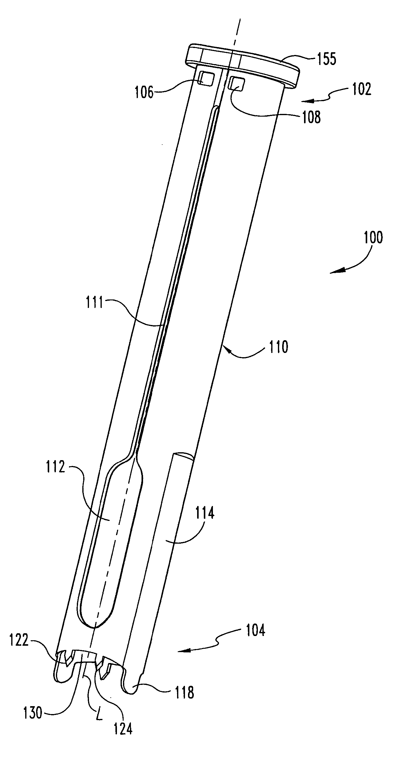
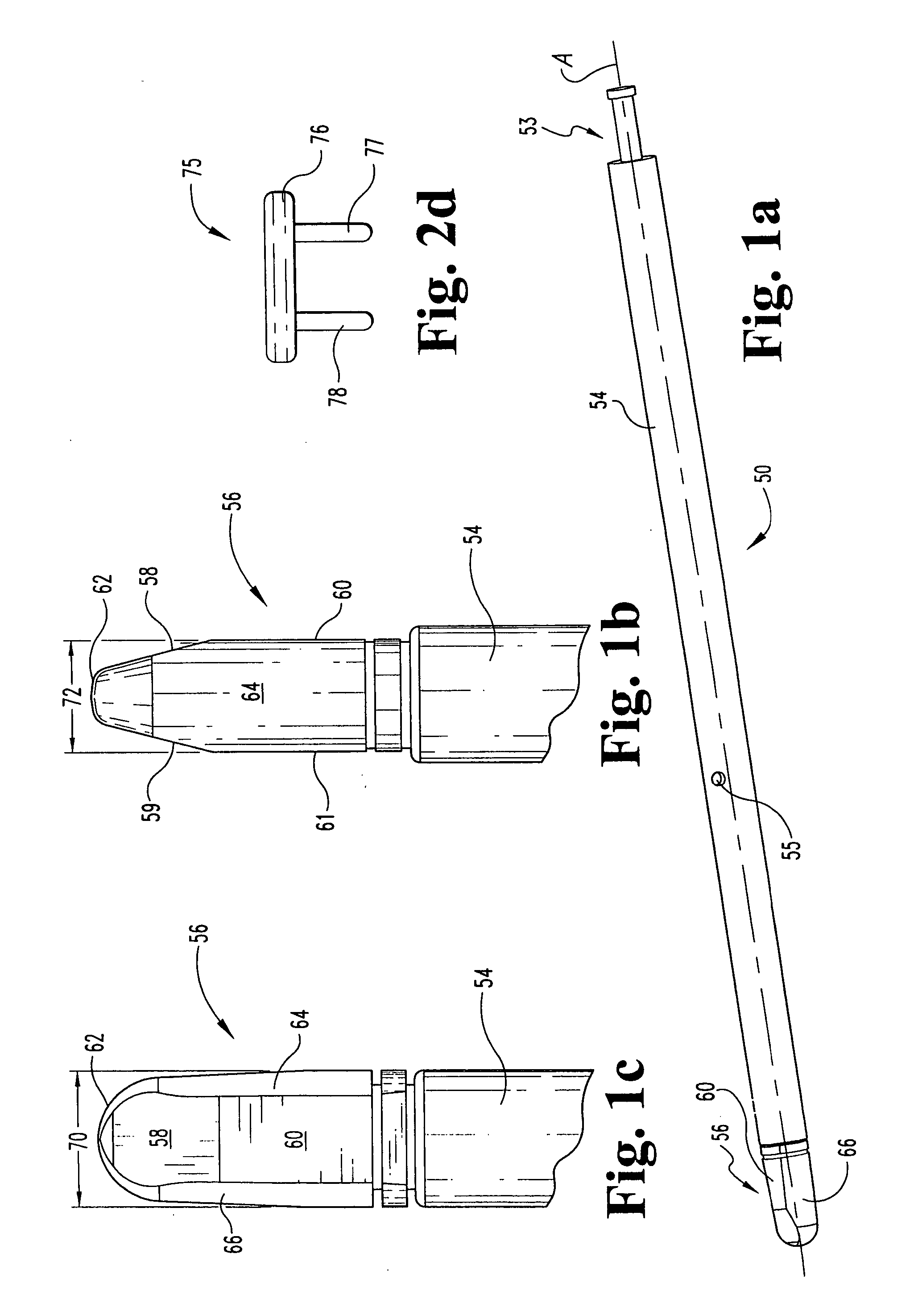
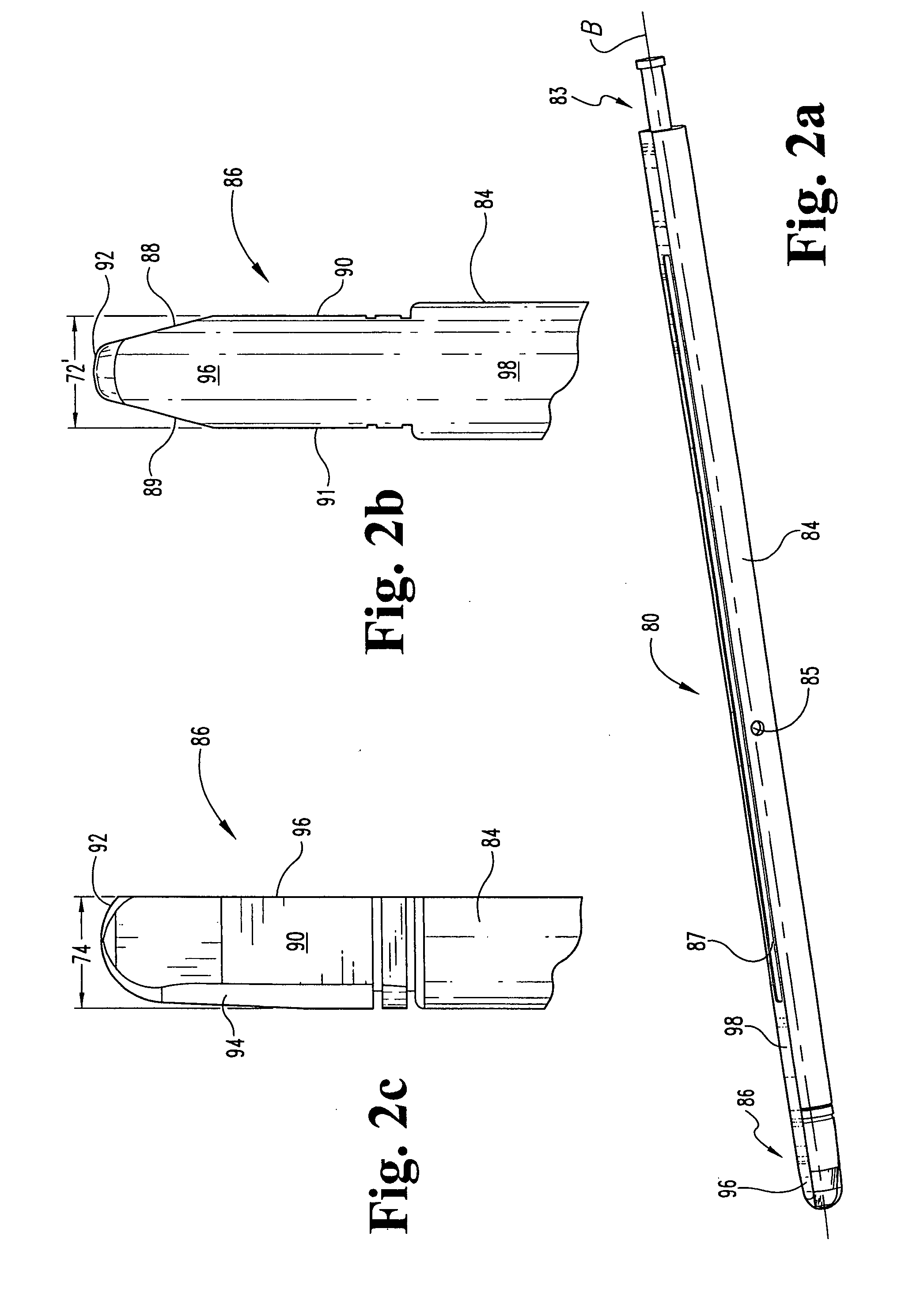
Methods and instrumentation particularly adapted for disc space preparation for insertion of implants from an anterior approach to the spine are provided. The instruments include a guide sleeve defining a channel having overlapping cylindrical working channel portions and lateral non-distracting extensions extending from reduced thickness wall portions. The guide sleeve has an overall reduced width configuration. A pair of distractors are provided. A first distractor includes a shaft and distal tip, each having convex walls. A second distractor includes a shaft and distal tip including a recessed area at least along the tip. The first distractor is at least partially received within the recessed area of the second distractor when the first and second distractors are in side-by-side relation and a reduced overall width of the distractors is obtained. Preferably, the first and second distractors are used with the guide sleeve. Methods using the disclosed instruments are also provided.

Description

CROSS-REFERENCE TO RELATED APPLICATIONS [0001] The present application is a divisional application of U.S. patent application Ser. No. 10 / 631,241 filed on Jul. 31, 2003, which is a divisional application of U.S. patent application Ser. No. 09 / 756,492 filed on Jan. 8, 2001 and now issued as U.S. Pat. No. 6,648,895; which is a continuation-in-part of U.S. patent application Ser. No. 09 / 498,426, filed Feb. 4, 2000, and now issued as U.S. Pat. No. 6,575,981; which claims the benefit of the filing date of U.S. Provisional Application Ser. No. 60 / 118,793, filed on Feb. 4, 1999, each of which is incorporated herein by reference.BACKGROUND OF THE INVENTION [0002] The present invention relates generally to surgical procedures for spinal stabilization and more specifically to instrumentation adapted for inserting a spinal implant within the intervertebral disc space between adjacent vertebra. More particularly, while aspects of the invention may have other applications, the present invention ...

Claims


Application Information

Patent Timeline
Patent Type & Authority Applications(United States)
IPC IPC(8): A61B17/56A61F2/44A61B17/00A61B17/02A61B17/16A61B17/17A61B19/00A61F2/00A61F2/30A61F2/46
CPCA61B17/025A61F2250/0063A61B17/1735A61B17/1757A61B2017/0256A61B2019/304A61B2019/446A61F2/442A61F2/446A61F2/4611A61F2002/30611A61F2002/3082A61F2002/3085A61F2002/30871A61F2002/30904A61F2002/4475A61F2002/448A61F2002/4623A61F2002/4627A61F2002/4681A61B17/1671A61B2090/034A61B90/94A61F2002/30604A61F2/4603A61F2002/30593
Inventor BURKUS, J. KENNETHZDEBLICK, THOMAS A.MCGAHAN, THOMAS V.DERIDDER, STEVEN D.
Owner WARSAW ORTHOPEDIC INC
Learn More