Quality of Service Monitor in a Packet-Based Network

a packet-based network and quality monitor technology, applied in the field of networks, can solve the problems of reducing the service quality of the monitor, invasive techniques injecting undesirable traffic into the network, and not providing punctual qos measurement per session, so as to improve the service quality and the service quality. the effect of scalability, efficient and low-cost, and high network scalability

Inactive Publication Date: 2007-12-13
TELECOM ITALIA SPA
View PDF4 Cites 33 Cited by
  • Summary
  • Abstract
  • Description
  • Claims
  • Application Information

AI Technical Summary

Benefits of technology

[0019] The Applicant has found that by using a three-tier architecture wherein one or more applications (herein below called “subscribers” or “watchers”) can request customized QoS reports from a quality server using a subscription request, and wherein, in response, the quality server prepares these reports based on QoS messages received from user terminals during their communications and sends the reports to the subscribers in the requested form, very flexible and low-cost QoS monitoring can be performed and high scalability of the network can be achieved.
[0020] The three-tier architecture of the present invention provides more scalability thanks to the presence of a mediation element, whereas with a two-tier architecture messages are directly exchanged by applications and terminals. Sca

Problems solved by technology

Packet loss rate resulting from congestion that is the maximum rate at which packets can be discarded during transfer through a network.
Unfortunately, these invasive techniques inject undesirable traffic on the network.
Additionally, these techniques do not provide a punctual per-session QoS measurement because the traffic injection is not synchronous with the actual traffic.
Finally, QoS measurement is of the injected traffic rather than the actual traffic, which further dilutes the value of the measurements.
Unfortunately, the use of probes has limited scalability because the probes are expensive to install and maintain.
There are several problems with the QoS so

Method used


Image

  • Quality of Service Monitor in a Packet-Based Network
  • Quality of Service Monitor in a Packet-Based Network
  • Quality of Service Monitor in a Packet-Based Network

Examples


Embodiment Construction

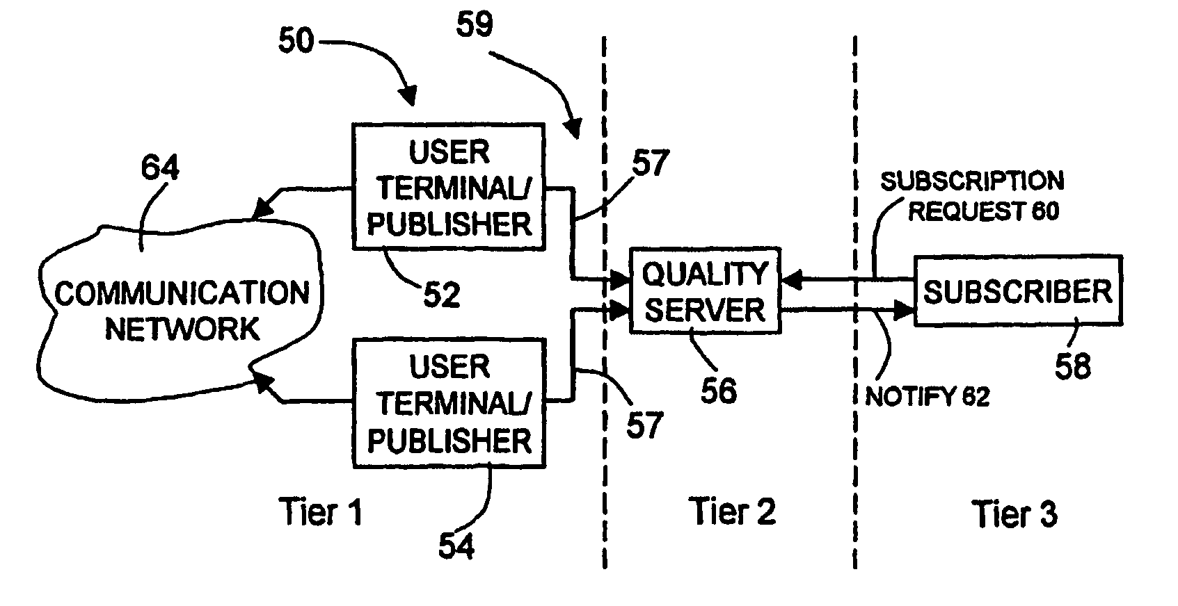
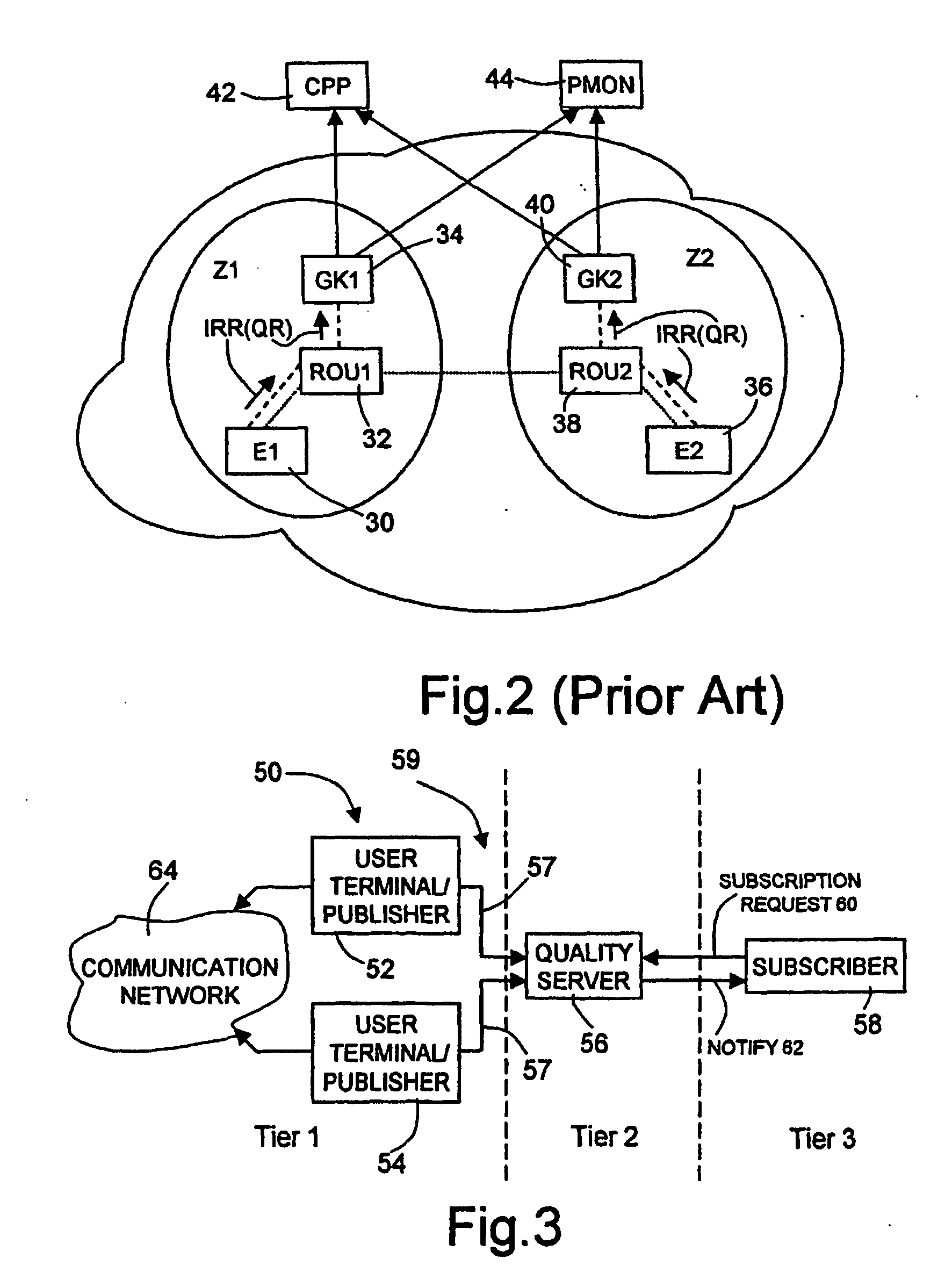
[0071] Referring to FIG. 3, a system 50 is shown having two user terminals 52, 54 that also function as publishers by collecting and publishing QoS information. The user terminals can be any type of communication device, such as IP phones, pagers, Instant Messaging clients, mobile phones, hand-held computing devices, etc. The user terminals send QoS information to a quality server 56 (also called “event server”) in the form of publish messages 57 using any desired protocol (e.g., SIP, H.323, JMS, etc.) over any desired packet-based network (shown generically at 59). As further described below, the quality server 56 is configured to receive QoS information from the user terminals and to generate quality reports there from. The quality server 56 is also coupled via a network to a subscriber 58, which is suitable to request from the quality server 56 specific QoS services to be notified by a quality report. In particular, the subscriber 58 is suitable to send a subscription request 60 ...


PUM


Abstract

A method and system of monitoring quality of service in a packet-based network includes a three-tier architecture, wherein one or more applications can request customized quality of service reports from a quality server. The customized reports may include, for example, a desired report format or trigger events indicating when the one or more applications should receive the report. The quality server prepares these reports based on quality of service messages received from user terminals and sends the reports in accordance with the request.

Description

TECHNICAL FIELD OF THE INVENTION [0001] The present invention relates generally to networks, and, more particularly, to monitoring quality of service (QoS) in a packet-based network. BACKGROUND ART [0002] Intense competition is expected in the information-networking arena over the next decade. As the competition increases, it is essential for companies to position themselves appropriately taking advantage of their core competencies and preparing for the emerging telecommunications technology. In this competitive environment, mergers, alliances, and new entrants in the market place have service providers searching for innovative ways to retain and attract subscribers. Today's service providers are striving to differentiate themselves within this expanding competitive landscape by searching for ways to bundle new services for their customer base. Consequently, many service providers are looking to Next Generation Networks (NGN) as a means to attract new customers. [0003] NGN is a term...

Claims


Application Information

Patent Timeline
IPC IPC(8): G06F15/173H04L12/14H04L12/24H04L12/26H04L29/06
CPCH04L12/1428H04L29/06H04L29/06027H04L41/5029H04L41/5067H04L65/80H04L43/0829H04L43/087H04L43/12H04L65/1006H04L43/06H04L65/1104H04L9/40H04L65/1101
Inventor DE NOIA, GIUSEPPEFUSCO, ANTONIOROASIO, ANDREA
Owner TELECOM ITALIA SPA
Why Eureka
Try Eureka