
Material handling assembly

a technology for material handling and assembly, which is applied in the direction of mechanical machines/dredgers, soil shifting machines/dredgers, constructions, etc., can solve the problems of increasing the cost of manufacture and installation, requiring a certain amount of manual labor for fixing, and comparatively expensive problems

Inactive Publication Date: 2007-12-20
MILLONZI INT PRODS GROUP
View PDF22 Cites 16 Cited by
  • Summary
  • Abstract
  • Description
  • Claims
  • Application Information

AI Technical Summary

Benefits of technology

"The present invention is a material handling assembly for a machine. It consists of a bucket, an arm, a bracket, a strut, and a conversion kit. The assembly is easy to install and adjustable, with a thumb that can be set at different angles for operational purposes. The technical effects of the invention are improved material handling efficiency, simplified construction, and easy installation."

Problems solved by technology

Utilizing a hydraulic cylinder for adjusting the angle of the thumb has a number of advantages but is comparatively costly.
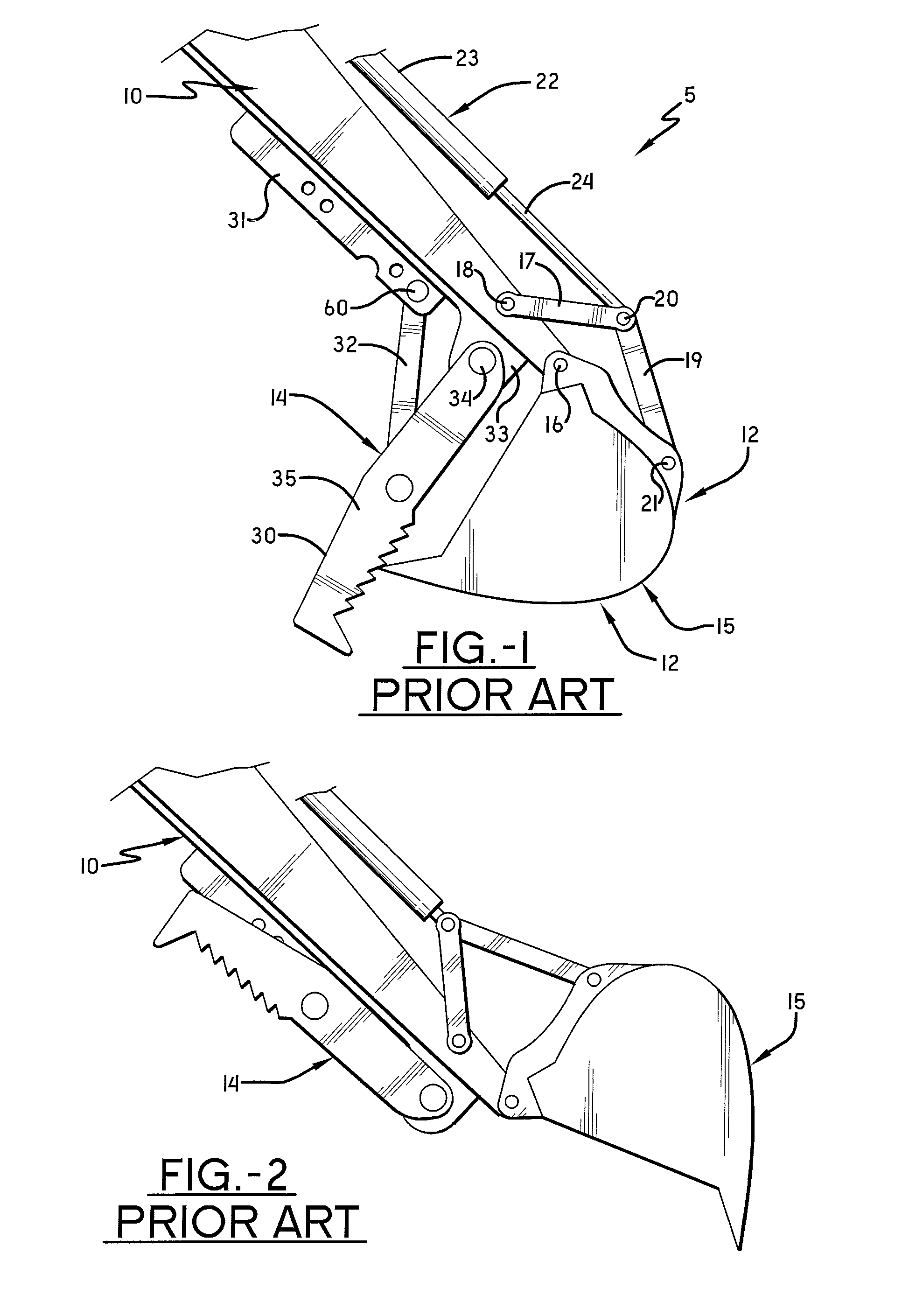
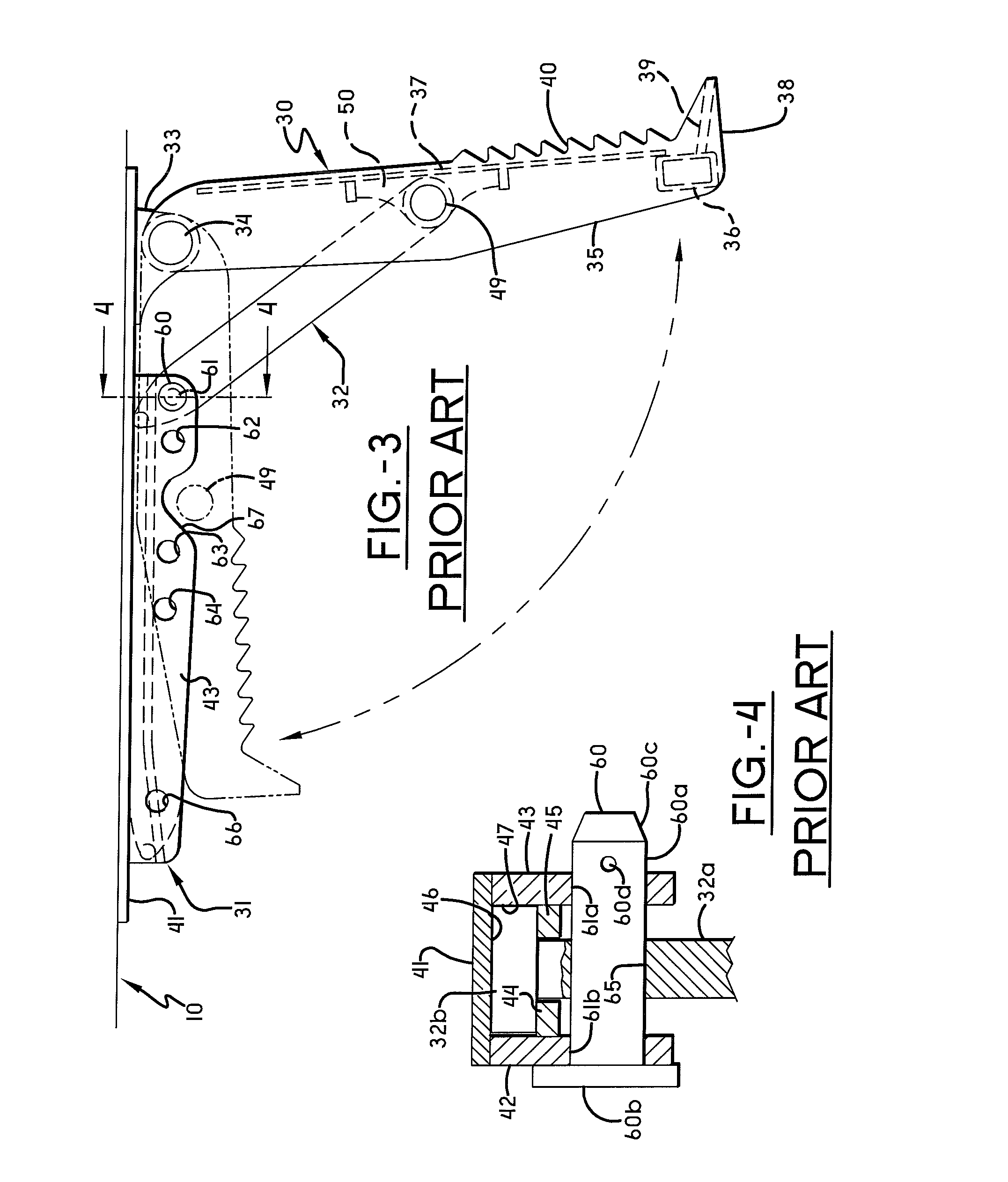
Utilizing a rigid strut and a number of connecting brackets also has a number of disadvantages including increased cost of manufacture and installation and a certain amount manual labor being required in fixing the desired angle of the thumb and securing it into position.
Another problem associated with material handling assemblies of the past, such as the one described in U.S. Pat. No. 6,203,267 is that it is difficult and time-consuming for the operator to reposition the strut relative to the openings in the bracket due to the weight of the components involved.
Given the weight of the strut and thumb and the need to hold it steady, it is often necessary to involve two or more workers to reposition the strut which is time consuming, inefficient and dangerous.
Moreover, the lateral forces being applied to the pin by the sidewalls of the openings in the strut often result in the pin becoming jammed and makes it even more difficult for the operator to remove the pin to reposition the thumb assembly relative to the arm.

Method used


Image

  • Material handling assembly
  • Material handling assembly
  • Material handling assembly

Examples


Embodiment Construction

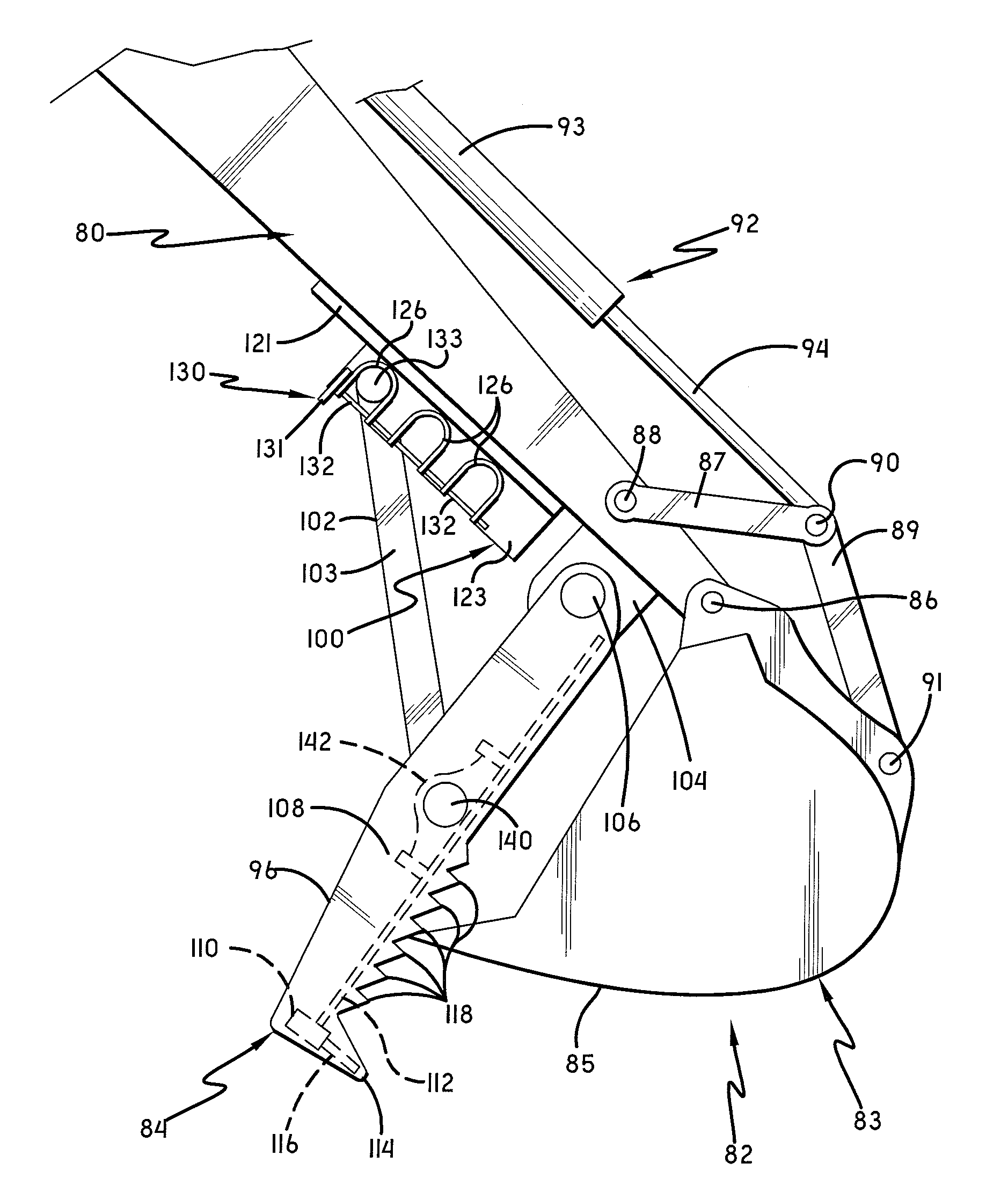
[0029]Referring now to the drawings wherein the showings are for purposes of illustrating various embodiments of the invention only and not for purposes of limiting the same, the figures illustrate the novel idea of a material handling assembly. The material handling assembly is an assembly mountable on the articulated arm of the machine consisting generally of a bucket pivotally connectable to the articulated arm of the machine and the means for pivoting the bucket about the pivotal connection of the bucket to the articulated arm, an arm member pivotally connectable to the articulated arm and cooperable with the bucket when mounted on the articulated arm for clamping material being handled therebetween, a bracket mountable on the underside of the articulated arm, having a guideway therealong, a strut having a first end thereof pivotally connected to the arm member and second end thereof received within and displaceable along the guideway, and means for detachably securing the secon...


PUM


Abstract

A material handling assembly is described herein. The material handling assembly provides an assembly mountable on the articulated arm of the machine consisting generally of a bucket pivotally connectable to the articulated arm of the machine and the means for pivoting the bucket about the pivotal connection of the bucket to the articulated arm, an arm member pivotally connectable to the articulated arm and cooperable with the bucket when mounted on the articulated arm for clamping material being handled therebetween, a bracket mountable on the articulated arm, a strut having a first end thereof pivotally connected to the arm member and second end thereof received within and displaceable along the bracket, and means for detachably securing the second end of the strut to the bracket at selected points along the length of the bracket in a safe and efficient manner.

Description

TECHNICAL FIELD[0001]The invention relates generally to an improved material handling assembly for use in connection with earth moving equipment such as excavators and backhoes and the like. More specifically, the invention relates to an improved material handling assembly that is attached to, and easily repositioned relative to an articulated arm of the earth moving equipment.BACKGROUND OF THE INVENTION[0002]Earth moving equipment such as excavators and backhoes are commonly used by contractors for various construction projects where it is desirable to move large amounts of materials such as soil, rocks, tree trunks and stumps and other debris. Such equipment typically includes a handle or arm-like structure, referred to herein as the articulated arm, extending from the main body of the equipment, a bucket pivotally connected to one end of the articulated arm and a hydraulic cylinder assembly to move or reposition the bucket relative to the articulated arm.[0003]It is also known in...

Claims


Application Information

Patent Timeline
Patent Type & Authority Applications(United States)
IPC IPC(8): E02F3/96
CPCE02F3/404
Inventor RIFFLE, LONNIE
Owner MILLONZI INT PRODS GROUP
Learn More