System and method for producing diesel exhaust for testing diesel engine aftertreatment devices

Active Publication Date: 2007-12-20
SOUTHWEST RES INST
View PDF71 Cites 20 Cited by
  • Summary
  • Abstract
  • Description
  • Claims
  • Application Information

AI Technical Summary

Problems solved by technology

The use of production diesel engines for such testing has presented many disadvantages including inconsistent operability, intensive maintenance, and expensive operating costs.

Method used


Image

  • System and method for producing diesel exhaust for testing diesel engine aftertreatment devices
  • System and method for producing diesel exhaust for testing diesel engine aftertreatment devices
  • System and method for producing diesel exhaust for testing diesel engine aftertreatment devices

Examples


Embodiment Construction

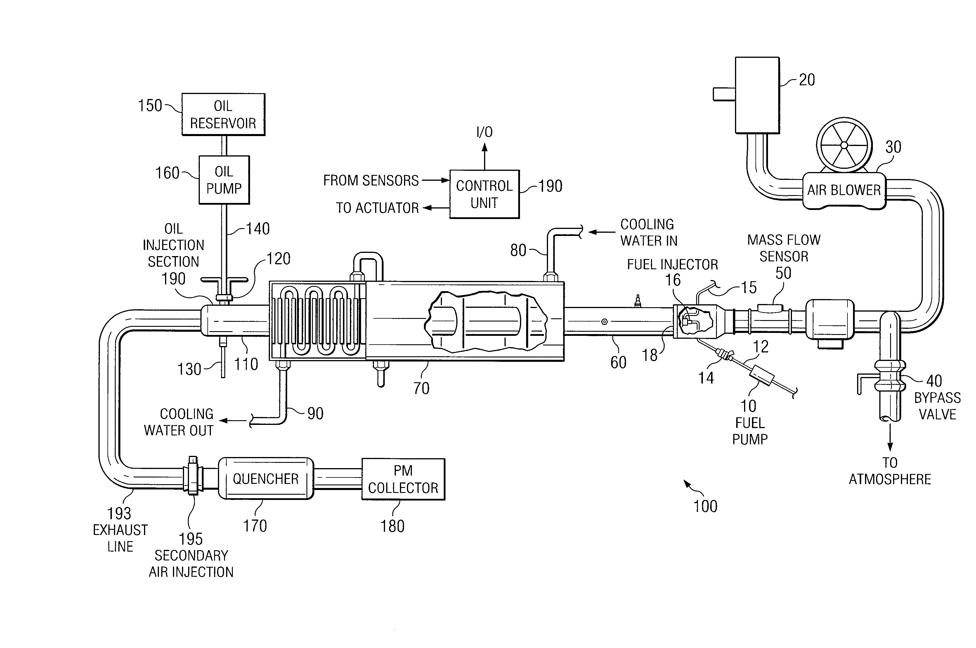
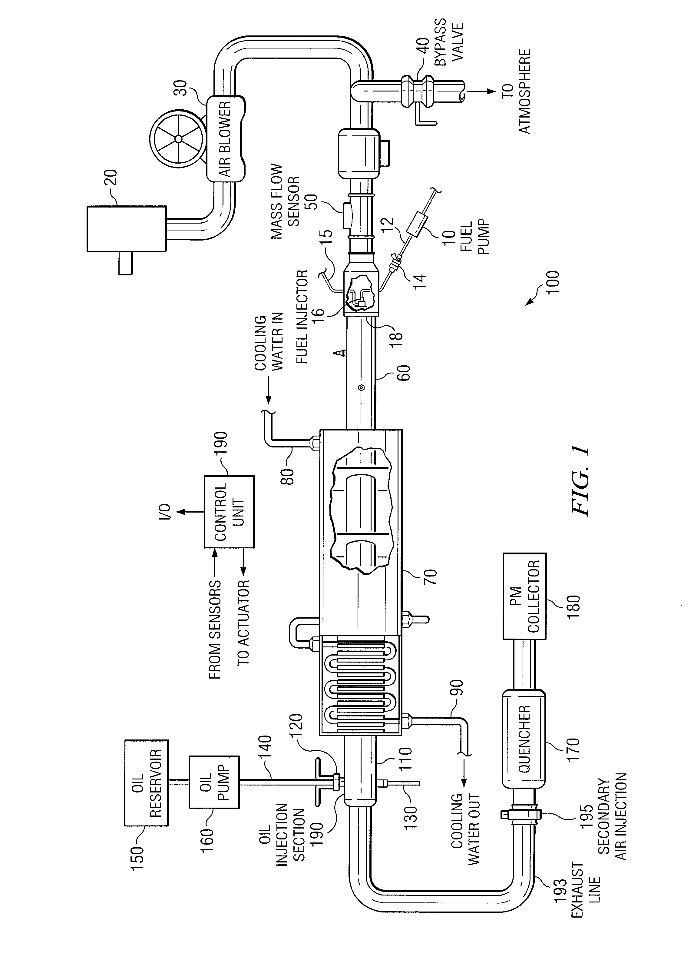
[0010] The following description is directed to using a burner-based system to produce diesel exhaust gas, typically for the purpose of testing diesel exhaust aftertreatment devices. The use of this system instead of a diesel engine lowers operating costs, reduces test variability, and increases control of the exhaust gas composition, pressure, mass flow rate, and temperature.

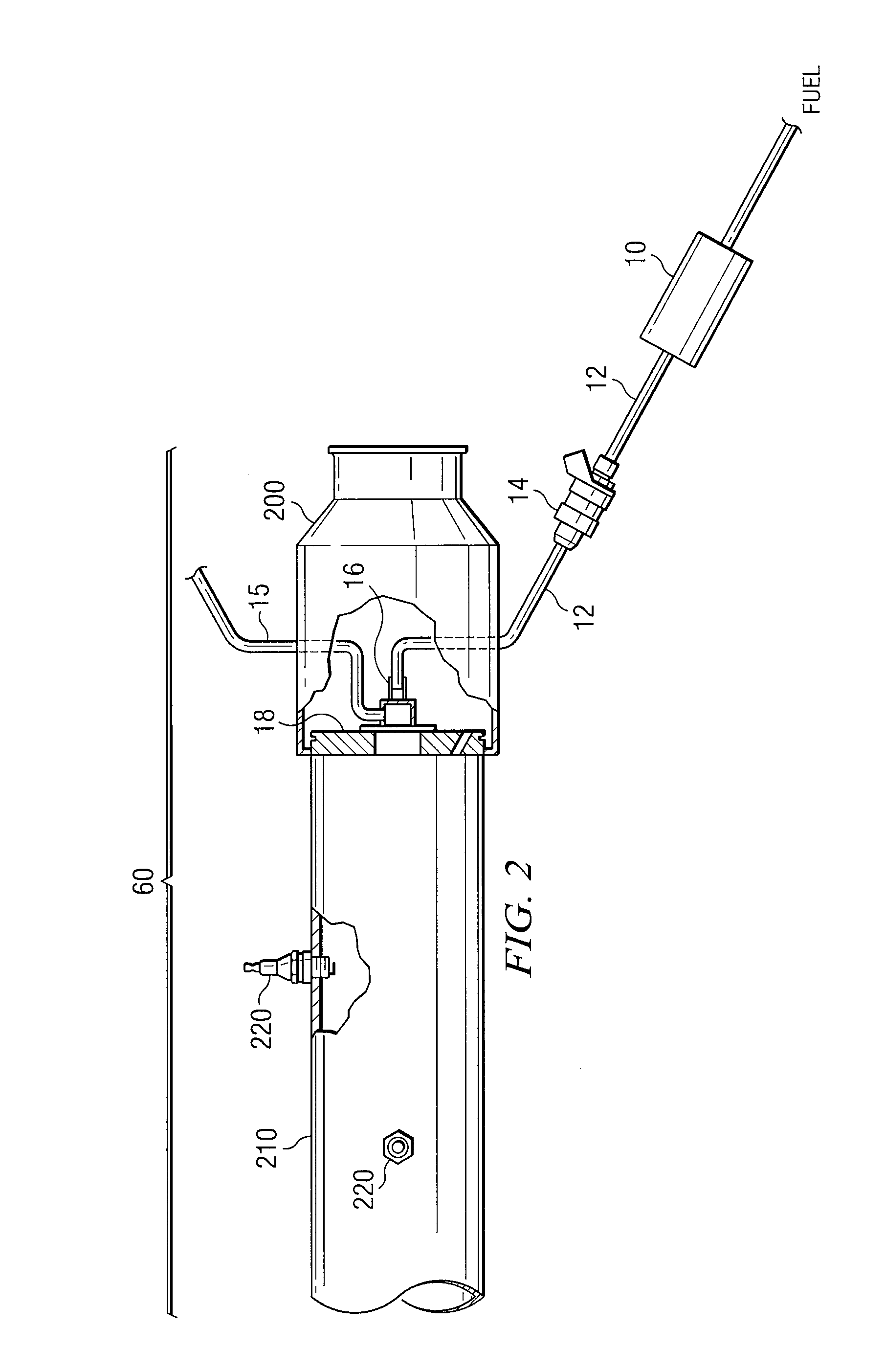
[0011] U.S. Patent Publication No. 2003 / 0079520, incorporated herein by reference, describes a burner-based exhaust generation system, without certain features described herein but otherwise suitable for testing exhaust aftertreatment devices. The system comprises: (1) an air supply system to provide air for combustion to the burner, (2) a fuel system to provide fuel to the burner, (3) a burner system to combust the air and fuel mixture and to provide the proper exhaust gas constituents, (4) a heat exchanger to control the exhaust gas temperature, (5) an oil injection system, and (6) a computerized control sys...


PUM


Abstract

A method of using a burner-based system to produce diesel exhaust gas that contains particulate matter of a desired composition, to simulate the PM matter in exhaust produced by a production-type diesel internal combustion engine.

Description

RELATED APPLICATION [0001] This application is a continuation-in-part of U.S. patent application Ser. No. 10 / 917,245 filed Aug. 12, 2004, which is a is a continuation-in-part of U.S. patent application Ser. No. 10 / 213,890, filed Aug. 6, 2002, which claims priority to 60 / 310,345 filed Aug. 6, 2001, the contents of which are hereby incorporated by reference. [0002] This application is related to co-pending U.S. patent application Ser. No. 11 / 470,471 filed Sep. 6, 2006; U.S. patent application Ser. No. 11 / 420,393 filed May 25, 2006; U.S. patent application Ser. No. 11 / 326,983 filed Jan. 6, 2006; U.S. patent application Ser. No. 10 / 917,230 filed Aug. 12, 2004; U.S. patent application Ser. No. 10 / 918,330 filed Aug. 12, 2004; U.S. patent application Ser. No. 10 / 847,034 filed May 17, 2004; U.S. patent application Ser. No. 10 / 458,023 filed Jun. 10, 2003; U.S. patent application Ser. No. 10 / 439,146 filed May 15, 2003, now U.S. Pat. No. 6,983,545 B2; and U.S. patent application Ser. No. 10 / 45...

Claims


Application Information

Patent Timeline
IPC IPC(8): F01N3/02G01M99/00
CPCF01N3/021F01N3/043F01N3/30Y10T436/25875F01N2550/20Y02T10/20F01N2260/20Y02T10/12
Inventor BARTLEY, GORDON JAMES JOHNSTONWEBB, CYNTHIA CHAFFINABDUL-KHALEK, IMAD
Owner SOUTHWEST RES INST
Why Eureka
Try Eureka