System and method for removing particulate matter from a diesel particulate filter

a technology of particulate matter and filter, which is applied in the field of aftertreatment systems, can solve the problems of poor diesel exhaust gas flow rate, inefficient diesel engine operation, and excessive trapped particulate matter in the filter of the conventional system, so as to reduce the energy loss, reduce the energy consumption, and reduce the effect of was

Active Publication Date: 2009-02-19
GE GLOBAL SOURCING LLC
View PDF14 Cites 33 Cited by
  • Summary
  • Abstract
  • Description
  • Claims
  • Application Information

AI Technical Summary

Benefits of technology

[0008]Another embodiment of the present invention provides a method for removing particulate matter from a diesel particulate filter. The diesel particulate filter includes at least one diesel particulate filter unit to filter the particulate matter from diesel engine exhaust gas received from a diesel engine of a locomotive. The method includes determining the extent of trapped particulate matter within the diesel particulate filter unit by positioning at least one sensor adjacent to the at least one of the diesel particulate filter unit. The method further includes creating a trip plan to optimize the performance of the locomotive along a route in accordance with a power setting of the diesel engine at each location along the route. The method further includes configuring each sensor to output a first alert signal to the engine controller upon the trapped particulate matter exceeding a predetermined threshold. The method further includes configuring the engine controller to communicate with a locomotive controller upon receiving the first alert signal to determine a time region or distance region within the trip plan when the power setting of the diesel engine is greater than a power threshold. Additionally, the method includes configuring the engine controller to increase the temperature of the diesel exhaust gas entering the diesel particulate filter during the time region or distance region upon receiving the first alert signal.

Problems solved by technology

After a prolonged period of operating time, the diesel particulate filter of the conventional system will become backlogged with excessive trapped particulate matter.
However, none of the conventional systems efficiently remove the trapped particulate matter from the diesel particulate filter, thus leading to a poor diesel exhaust gas flow rate and inefficient diesel engine operation.

Method used


Image

  • System and method for removing particulate matter from a diesel particulate filter
  • System and method for removing particulate matter from a diesel particulate filter
  • System and method for removing particulate matter from a diesel particulate filter

Examples


Embodiment Construction

[0020]Reference will now be made in detail to the embodiments consistent with the invention, examples of which are illustrated in the accompanying drawings. Wherever possible, the same reference numerals used throughout the drawings refer to the same or like parts.

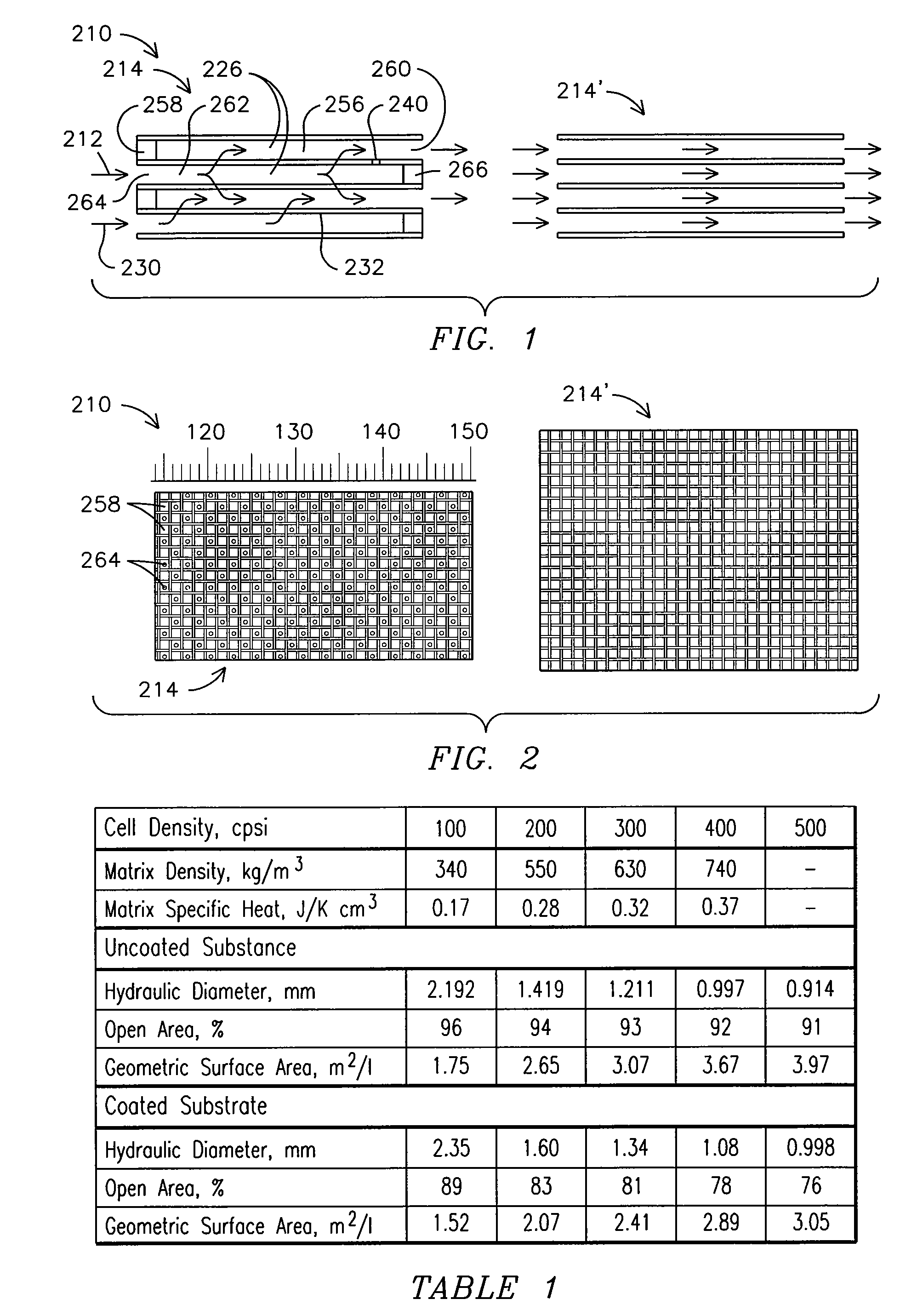
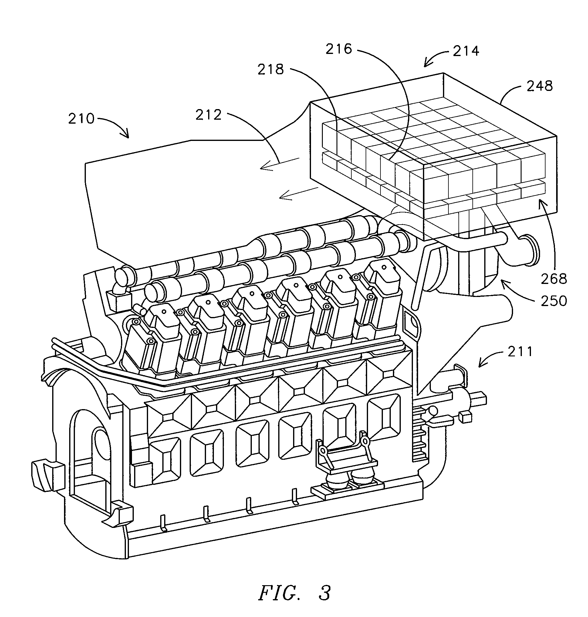
[0021]FIGS. 1 and 2 illustrate exemplary embodiments of a wall-flow diesel particulate filter 214 and a flow-through diesel particulate filter 214′. The diesel particulate filter 214 illustrated in the exemplary embodiment of FIGS. 1 and 2 is an example of an aftertreatment system, and similar examples may be constructed for wall-flow diesel particulate filters, to chemically reduce any or all species in the diesel engine exhaust, such as hydrocarbons, CO, nitrous dioxide, and other chemicals appreciated by one of skill in the art, as further discussed below in additional embodiments of the present invention. As illustrated in FIG. 1, a diesel particulate filter unit 216 (FIG. 3) includes a plurality of channels 226 aligne...


PUM


Abstract

A system is provided for removing particulate matter from a diesel particulate filter. The system includes an engine controller coupled to the diesel engine, and to a locomotive controller. The locomotive controller includes an algorithm to create a trip plan to optimize the performance of the locomotive along a route in accordance with a power setting of the diesel engine at each location along the route. Each sensor is configured to output a first alert signal to the engine controller once the trapped particulate matter exceeds a predetermined threshold. Upon receiving the first alert signal, the engine controller communicates with the locomotive controller to determine a time region or distance region within the trip plan when the power setting exceeds a power threshold. The engine controller increases the temperature of the diesel exhaust gas entering the diesel particulate filter during the time region or distance region.

Description

[0001]This application is related to U.S. patent application Ser. Nos. 11 / 838,277 (Attorney Docket No. 226286-1 (590) and Ser. No. ______ (Attorney Docket No. 226266-1 (593), filed concurrently herewith. Each of the foregoing applications is incorporated by reference herein in their entirety.FIELD OF THE INVENTION[0002]This invention relates to aftertreatment systems, such as a diesel particulate filter, and more particularly to a system and method for removing particulate matter from a diesel particulate filter.BACKGROUND OF THE INVENTION[0003]Diesel engines have been extensively used in various applications, such as locomotives, for example. Diesel engine exhaust gas is typically outputted from the engine (or a turbocharger connected to the diesel engine) and directed to an output, such as to the atmosphere for a locomotive diesel engine, for example.[0004]More stringent emissions standards on diesel engines have led to the introduction of aftertreatment systems to reduce emission...

Claims


Application Information

Patent Timeline
Patent Type & Authority Applications(United States)
IPC IPC(8): F01N3/035F02B33/00F02D41/00G05D1/02
CPCF01N3/023F01N3/025F01N3/035F01N9/002F01N2590/08F01N2560/08F01N2560/14F01N2900/0422Y02T10/47F01N2560/06Y02T10/40
Inventor GALLAGHER, SHAWN MICHAELPRIMUS, ROYTOPINKA, JENNIFER
Owner GE GLOBAL SOURCING LLC
Why Eureka
Try Eureka