Bifilar diesel exhaust filter construction using sintered metal fibers

a technology of metal fibers and bifilar diesel, which is applied in the direction of filtration separation, auxillary pretreatment, separation processes, etc., can solve the problems of high initial cost, high energy consumption and high maintenance cost, and insufficient passive particulate filters, etc., to improve overall performance, improve the overall performance, and improve the effect of particle holding capacity

Inactive Publication Date: 2005-09-13
RYPOS
View PDF28 Cites 34 Cited by
  • Summary
  • Abstract
  • Description
  • Claims
  • Application Information

AI Technical Summary

Benefits of technology

[0010]The present invention preserves the advantages of prior art electrically regenerated diesel particulate filter constructions. In addition, it provides new advantages not found in currently available filter constructions, and overcomes many disadvantages of such currently available filter constructions and related systems.
[0011]The invention is generally directed to a novel and unique self-cleaning particle filter construction with particular application in removing carbon, lube oil and unburned fuel particulates from the exhaust of Diesel engines. The self-cleaning particle filter construction of the present invention enables the inexpensive assembly, use and maintenance of a compact self-cleaning particle filter constructions for use in filtration systems for Diesel engines without detracting from the overall performance of the engine or the fuel economy thereof.

Problems solved by technology

Unlike with gasoline engine vehicles, existing catalytic converters do not work well with Diesel engines since particulates typically clog these devices since the temperatures within them are too low to effectively burn carbon, lube oil and unburned fuel particles.
Such combustion chambers suffer from the drawbacks of high initial cost, safety, complexity, high-energy consumption and high maintenance cost.
These passive particulate filters are inadequate because when the filter fills up with carbon particles, the back pressure within the exhaust increases to such a level which necessitates that the filter be either regenerated in some fashion or replaced entirely.
Since replacing the filter is not practical, many types of regeneration have been attempted, including the raising of the temperature of the filter above the combustion point of the carbon particulates in similar fashion to a self-cleaning oven.
These prior art methods of filter regeneration include using a fired burner assembly using some type of fuel; raising the exhaust gas temperature by engine management, injecting fuel in the exhaust stream, or by electrical heating; Also by reducing the ignition temperature of carbon particles by adding heavy metal catalysts to the fuel and / or by coating filter material with suitable precious metal catalysts; The foregoing methods of filter regeneration have several disadvantages including low safety in the case of burners and fuel injection, unknown health effects in the case of heavy metal additives, and complexity in the case of using combination of these methods.
Heating the filter media indirectly results in long regeneration time, high energy consumption and incomplete regeneration.
The necessity for separate heater wires requires a much more complex construction than a passive filter construction which has no such heater wires.
Further, this electrical interconnection of the heater wires adds complexity to the circuit design of the filter media construction and the assembly into which it is installed.
Thus, in these prior art multiple layer assemblies, it is difficult to electrically isolate the layers for controlled independent heating.
As a result, prior art multiple layer filter constructions are complex to design and more expensive to manufacture.

Method used


Image

  • Bifilar diesel exhaust filter construction using sintered metal fibers
  • Bifilar diesel exhaust filter construction using sintered metal fibers
  • Bifilar diesel exhaust filter construction using sintered metal fibers

Examples


example

[0044]

Using a DC Power source of 12 volts, theLayer 1Layer 2following results were achieved:(inside)(outside)Material UsedFilterFiltermedia Amedia BResistance (ohms)0.20.1Heat Generated (watts)320160Temperature (degree C.)800600

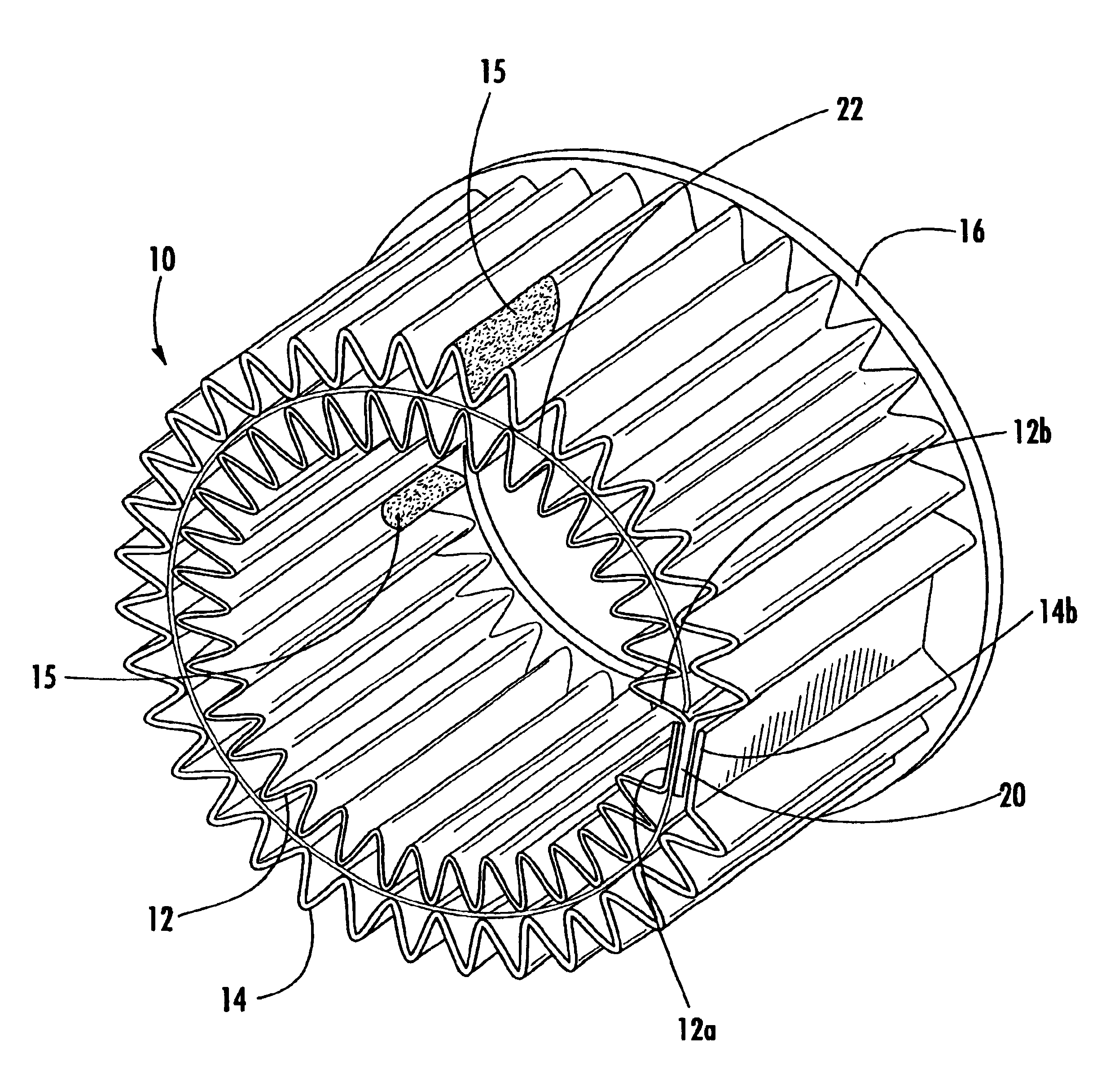
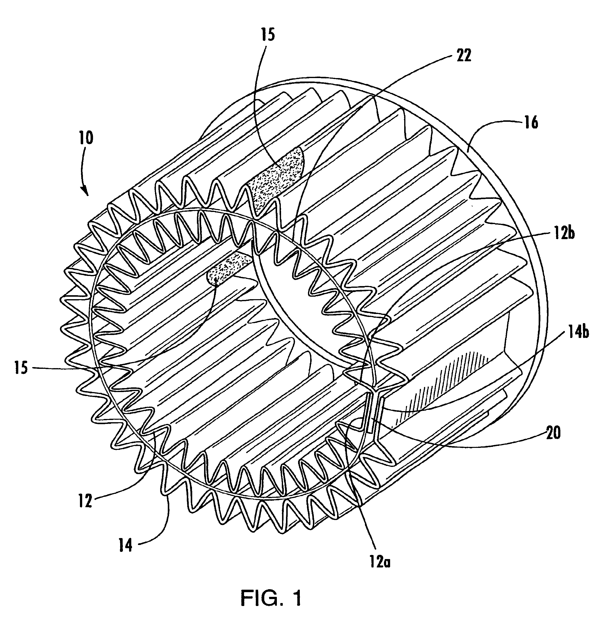
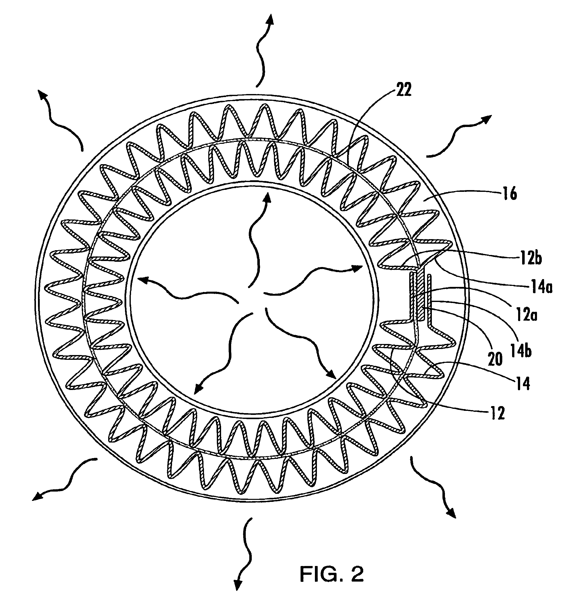
[0045]As can be seen from the foregoing data, it is possible to adjust the heat generated by the layers 12, 14 by modifying the characteristics of the layer. Such adjustment may be desired to control the amount of regeneration for a given layer 12, 14. For example, it may be desirable for the downstream layer to have higher heat because heat is lost across the filter construction10. On the other hand, the upstream layer may not need as much heat for regeneration because there is less power loss closest to the source of the exhaust flow. With the present invention, the regeneration of the layers 12, 14 may be finely controlled.

[0046]In a given layer, the material itself may be modified. For example, the layers 12, 14 may use different types of metal sintered a...


PUM

PropertyMeasurementUnit
temperaturesaaaaaaaaaa
electrically resistiveaaaaaaaaaa
electrically connectedaaaaaaaaaa

Abstract

A diesel particulate filter construction, for filtering particulate from a flow of exhaust, includes a first layer of electrically resistive metal filter material in line with the flow of exhaust with particulate therein and a second layer of electrically resistive filter material which is also in line with the flow of exhaust with particulate therein. The layers are pleated cylinders concentrically positioned relative to one another. Current from a power supply is routed through the first layer and the second layer, which are electrically connected in series to one another. The layers are positioned so that exhaust flows through both the layers. Sufficient heat is generated by the flow of current through the layers to generate heat to, in turn, burn off entrapped particulate. The layers may be made of made of different materials of different fiber sizes or coated with different catalysts to generate different amounts of heat from one another to improve the filtration characteristics of the particulate filter construction.

Description

CROSS REFERENCE TO RELATED APPLICATIONS[0001]This application claims the benefit of U.S. Provisional Patent Application Ser. No. 60 / 417,723, filed Oct. 10, 2002 and U.S. Provisional Patent Application Ser. No. 60 / 373,472, filed Apr. 18, 2002.BACKGROUND OF INVENTION[0002]The present invention relates generally to acapsBMcapsBMn electrically regenerable filter assembly. More specifically, the present invention relates to the regenerable self-cleaning filter construction that can be employed in a filter system for removing carbon, lube oil and unburned fuel particulates from the exhaust of internal combustion engines. In addition, the present invention relates to a regenerable filter construction for removing particulates from Diesel engine exhaust gases.[0003]In the automotive industry, there has been a tremendous concern over the introduction of harmful pollutants into the air which have been generated by vehicle exhaust. Due to the negative health effects of such emissions, the Envi...

Claims


Application Information

Patent Timeline
Patent Type & Authority Patents(United States)
IPC IPC(8): B01D46/52B01D46/50B01D46/00B01D46/24
CPCB01D46/0024B01D46/0063B01D46/2411B01D46/521B01D2279/30Y10S55/30Y10S55/10B01D46/84B01D46/64
Inventor PETER, KLAUS J.IBRAHIM, OSAMAWILLEY, PETERNARDI, ZACHARYSAEID, AMIN
Owner RYPOS
Why Eureka
Try Eureka