Burner for a Diesel Aftertreatment System

a diesel aftertreatment and burner technology, applied in the direction of engines, mechanical equipment, machines/engines, etc., can solve the problem of system limitation

Inactive Publication Date: 2011-03-17
TENNECO AUTOMOTIVE OPERATING CO INC
View PDF4 Cites 34 Cited by
  • Summary
  • Abstract
  • Description
  • Claims
  • Application Information

AI Technical Summary

Benefits of technology

[0023]In accordance with one feature of the invention, a method is shown for providing burners for use in at least two diesel exhaust gas treatment systems having different operating

Problems solved by technology

However, such systems become limited at temperatures below 300° C. and typically produce a pressure d

Method used


Image

  • Burner for a Diesel Aftertreatment System
  • Burner for a Diesel Aftertreatment System
  • Burner for a Diesel Aftertreatment System

Examples


Embodiment Construction

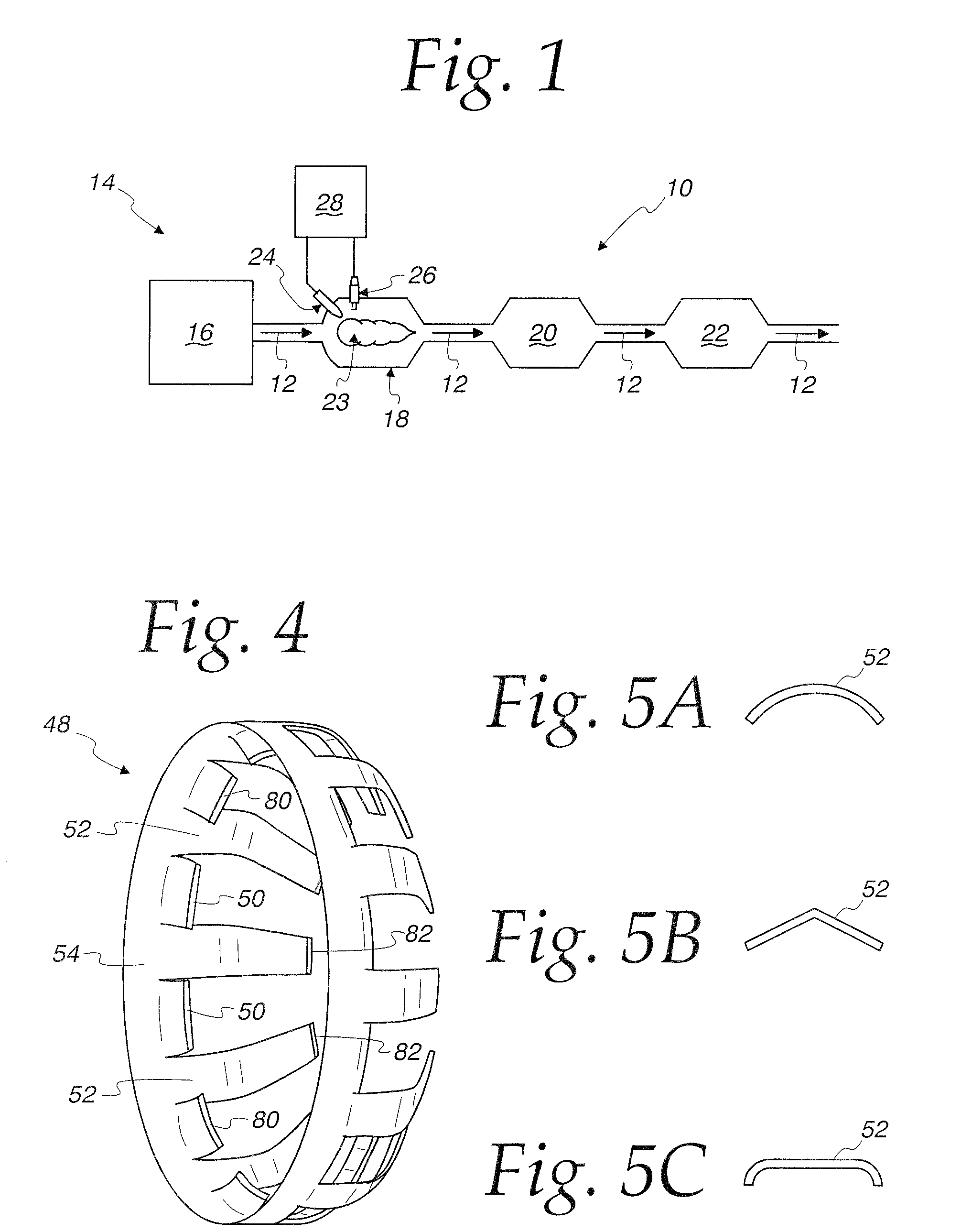
[0035]FIG. 1 shows a diesel exhaust gas aftertreatment system 10 for treating the exhaust 12 from a diesel combustion process 14, such as a diesel compression engine 16. The exhaust 12 will typically contain oxides of nitrogen (NOx) such as nitric oxide (NO) and nitrogen dioxide (NO2) among others, particular matter (PM), hydrocarbons, carbon monoxide (CO), and other combustion byproducts.

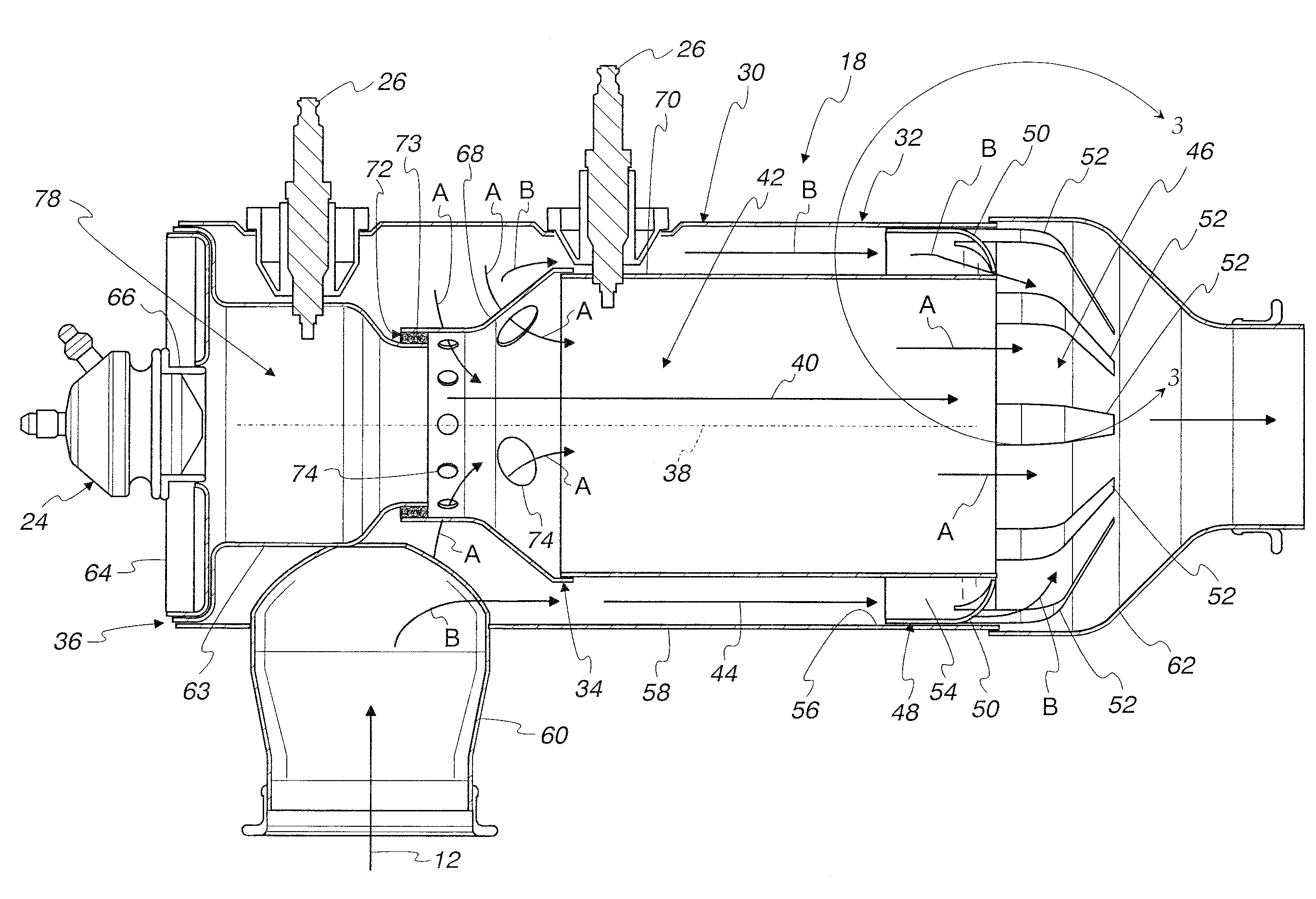
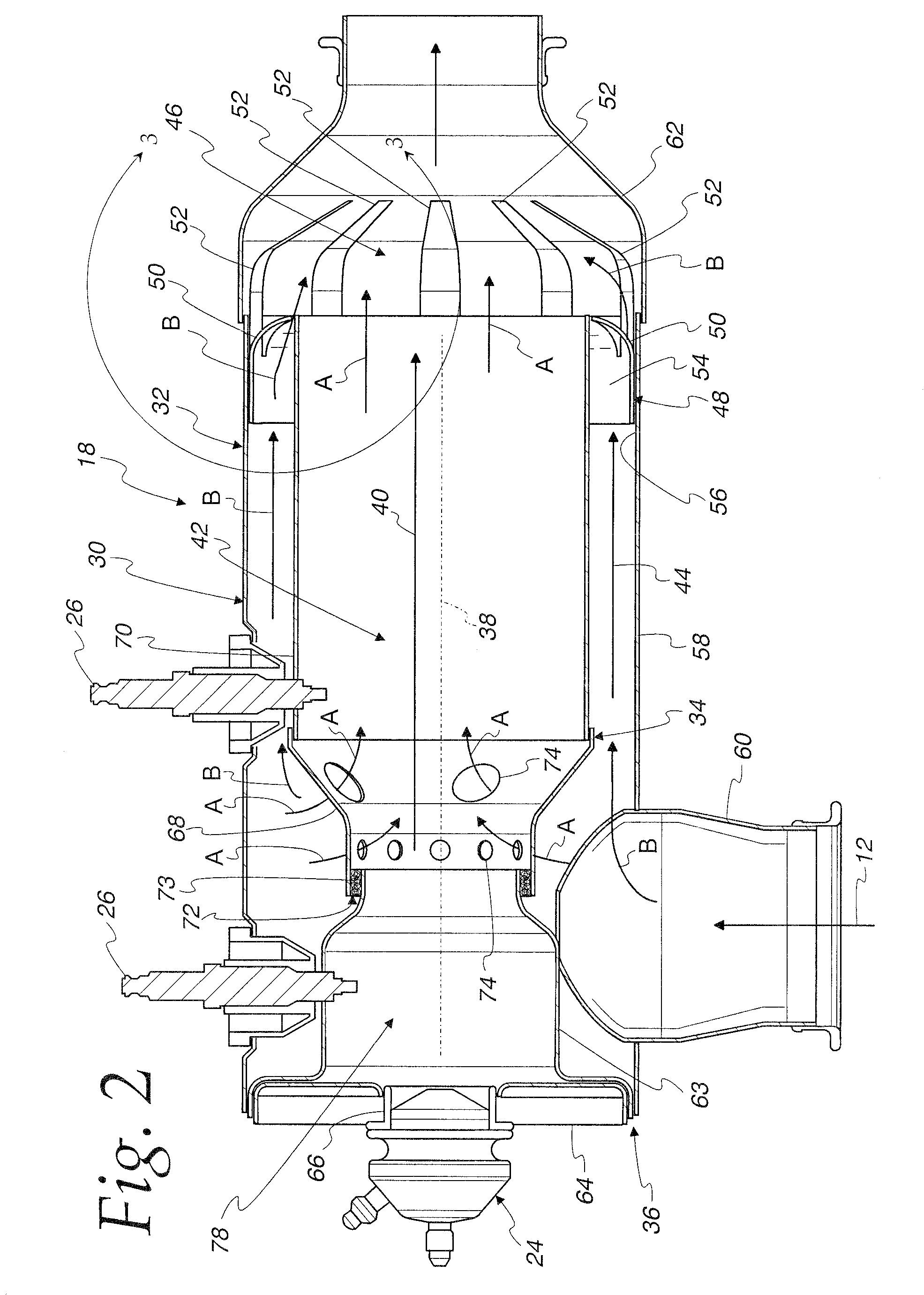
[0036]The system 10 includes a burner 18 that selectively supplies the exhaust 12 at an elevated temperature to the rest of the system 10 by selectively igniting and combusting fuel in the exhaust 12, wherein the fuel is introduced into the exhaust 12, and / or carried in the exhaust 12 as unburned fuel from the combustion products. The ability to provide the exhaust 12 at an elevated temperature to the rest of the system 10 provides a number of advantages, some of which will be discussed in more detail below.

[0037]The system 10 also preferably includes one or more other exhaust treatment devices, su...


PUM

PropertyMeasurementUnit
Lengthaaaaaaaaaa
Shapeaaaaaaaaaa
Areaaaaaaaaaaa

Abstract

A burner (18) is provided for use in a diesel exhaust gas treatment system (10) to treat an exhaust flow (12) from a diesel combustion process (14). The burner (18) includes an inner housing (34) defining a combustion flow path (40) to direct a first portion of the exhaust flow (12) through an ignition zone (42) wherein fuel is ignited, an outer housing (32) surrounding the inner housing (34) to define an annular bypass flow path (44) between the inner and outer housings (34, 32) to bypass a second portion of the exhaust flow (12) around the ignition zone (42), and a mixer (48) including a plurality of flow restrictor fingers (50) that extend across the bypass flow path (44) to restrict an available flow area of the bypass flow path (44), and a plurality of mixer fingers (52) having portions that extend inwardly from a location downstream from the inner housing (34).

Description

CROSS-REFERENCE TO RELATED APPLICATIONS[0001]This application claims the benefit of the filing date of U.S. Provisional Application No. 61 / 276,645, filed Sep. 15, 2009, which is hereby incorporated by reference in its entirety.FEDERALLY SPONSORED RESEARCH OR DEVELOPMENT[0002]Not Applicable.MICROFICHE / COPYRIGHT REFERENCE[0003]Not Applicable.FIELD OF THE INVENTION[0004]This invention relates to systems and methods for treating exhaust gases from a diesel combustion process, such as a diesel compression engine, and more particularly to systems for reducing oxides of nitrogen (NOx) and particulate matter (PM) emissions from diesel compression engines.BACKGROUND OF THE INVENTION[0005]Environmental regulations have called for increasing emission limits that require reduction in the NOx and PM from diesel combustion processes, and in particular from diesel compression engines. While diesel particulate filters (DPF) are capable of achieving the required reductions in PM, which is typically ...

Claims


Application Information

Patent Timeline
IPC IPC(8): F01N3/00F01N1/00B01F23/10
CPCF01N2240/14F01N3/025
Inventor YETKIN, DERVIS A.ANDERSON, GINETTE ALYCE
Owner TENNECO AUTOMOTIVE OPERATING CO INC
Why Eureka
Try Eureka