Subsea well with electrical submersible pump above downhole safety valve

a submersible pump and submerged well technology, applied in underwater drilling, drilling machines and methods, borehole/well accessories, etc., can solve problems such as subsea well shut down, internal formation pressure decline, and production reduction

Active Publication Date: 2007-12-20
BAKER HUGHES INC
View PDF12 Cites 60 Cited by
  • Summary
  • Abstract
  • Description
  • Claims
  • Application Information

AI Technical Summary

Benefits of technology

[0008]In this invention, a subsea well has a string of production tubing and a subsea safety valve located therein a selected distance below the wellhead assembly. When the production declines to an unsatisfactory level, an ESP is installed in an operational position within the production tubing above the valve. The ESP boosts well fluid pressure while the valve is open. Closing the valve enables the pump assembly to be installed within the well while live, because the valve serves as a pressure barrier. This feature allows the operator to install an ESP within a subsea well that is live without first killing the well.

Problems solved by technology

Because of the expense of offshore oil and gas drilling, most wells have sufficient internal formation pressure to flow naturally.
However, the internal formation pressure declines as the well fluid is produced over time.
Consequently, there are subsea wells that have been shut in because the internal pressure was not adequate.
The reduction in production is due not only to a decline in reservoir pressure, but also because of an impairment of the reservoir and / or an increase in fluid gradient.
One or a combination of these factors can render the well unable to produce fluid to the processing facility.
This is particularly a problem in very deep water where even if the pressure at the wellhead is positive, it may be inadequate to flow the reservoir fluid to a floating production vessel at the surface.
However, killing a well can cause damage to the formation from the kill fluid.
Because of the risk, killing a live subsea well to install an ESP is not normally done.
There have also been proposals to install ESPs in live land wells using various techniques, but these proposals are not easily applicable to subsea wells with subsea production trees.
If the hydraulic fluid pressure fails, the valve will close.
Consequently, in the event that the wellhead assembly is damaged, or if the hydraulic fluid pressure is lost, the valve will close.

Method used


Image

  • Subsea well with electrical submersible pump above downhole safety valve
  • Subsea well with electrical submersible pump above downhole safety valve
  • Subsea well with electrical submersible pump above downhole safety valve

Examples


Embodiment Construction

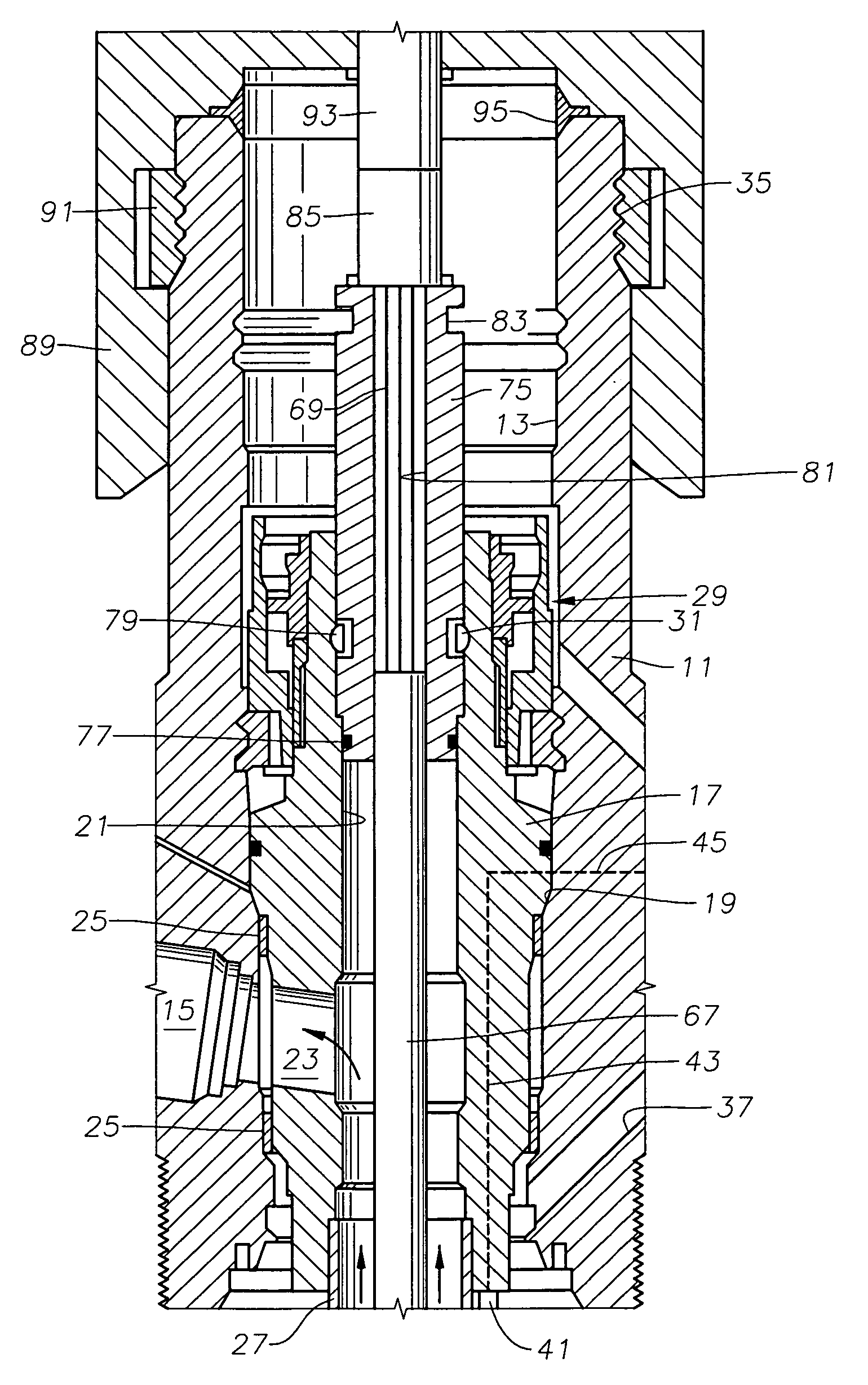
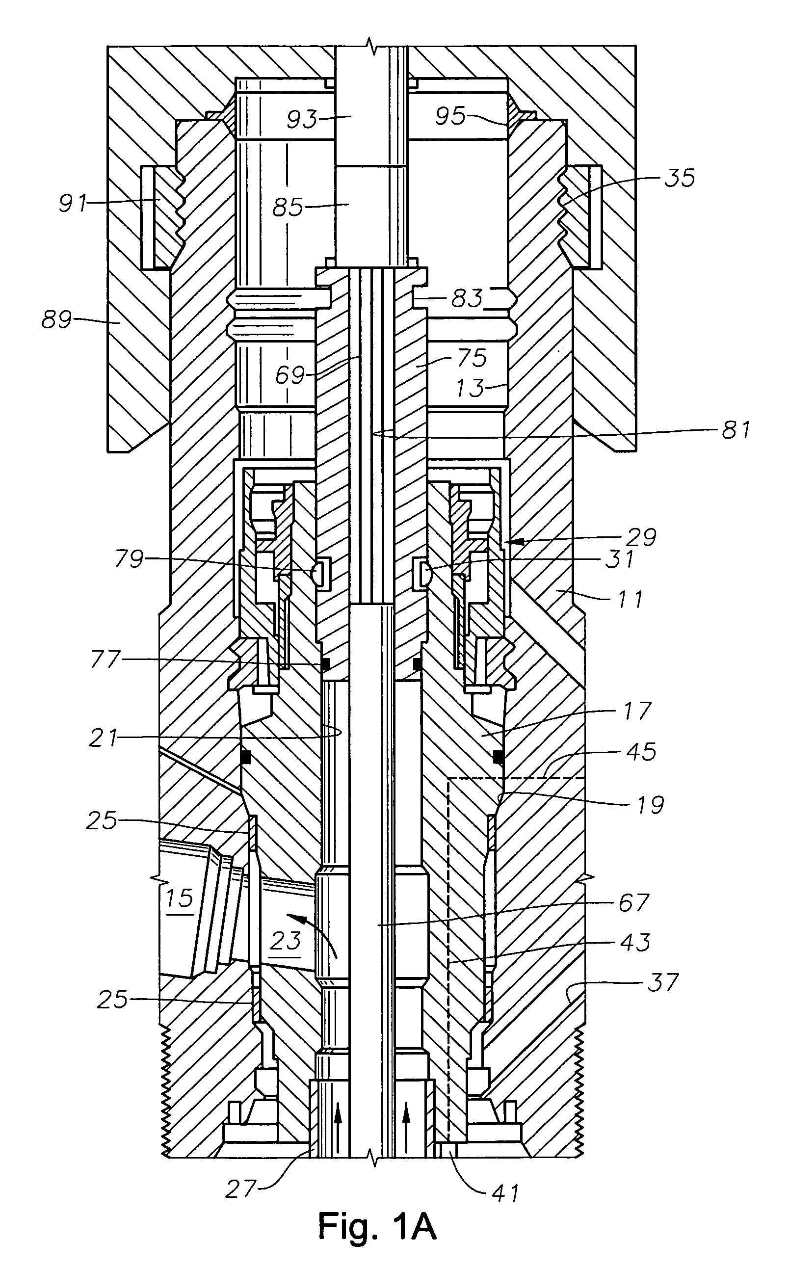
[0011]Referring to FIG. 1A, a portion of a subsea well assembly is illustrated. In this example, the subsea wellhead assembly comprises a production or Christmas tree 11. Tree 11 has a bore 13 extending through it and lands on a high pressure wellhead housing (not shown) located on this sea floor. Tree 11 has a lateral flow passage 15 that extends laterally outward through its side wall from bore 13.

[0012]In this example, a production tubing hanger 17 lands in bore 13 of tree 11 on a landing shoulder 19. The tubing hanger lands on a shoulder in the high pressure wellhead housing with another type of tree (not shown). Production tubing hanger 17 has a vertical or axial flow passage 21. A lateral flow passage 23 extends laterally from vertical flow passage 21 and registers with tree lateral flow passage 15. Tree 11 has various valves (not shown) for controlling the flow of well fluid through lateral flow passage 15. Production tubing hanger 17 has external seals 25 that seal above and...


PUM


Abstract

A subsea well production system has a natural drive mode and a lift-assist mode using a submersible pump. The submersible pump can be installed while the well is live. The well system has a downhole safety valve in the production tubing. The operator closes the downhole safety valve and lowers an electrical submersible pump assembly into the production tubing. Once landed, the valve is opened and the pump assembly placed in operation.

Description

FIELD OF THE INVENTION[0001]This invention relates in general to submersible well pump installations, and in particular to a submersible well pump located within production tubing above a downhole safety valve.BACKGROUND OF THE INVENTION[0002]Because of the expense of offshore oil and gas drilling, most wells have sufficient internal formation pressure to flow naturally. However, the internal formation pressure declines as the well fluid is produced over time. Consequently, there are subsea wells that have been shut in because the internal pressure was not adequate. Also there are subsea wells that continue to produce but at a rate below their actual potential. The reduction in production is due not only to a decline in reservoir pressure, but also because of an impairment of the reservoir and / or an increase in fluid gradient. One or a combination of these factors can render the well unable to produce fluid to the processing facility. This is particularly a problem in very deep wate...

Claims


Application Information

Patent Timeline
Patent Type & Authority Applications(United States)
IPC IPC(8): E21B29/12
CPCE21B43/128E21B34/06E21B43/16
Inventor SHAW, CHRIS K.SMITH, MICHAEL V.
Owner BAKER HUGHES INC
Why Eureka
Try Eureka