
Liquid crystal display device with patterned black matrix for sealant

a liquid crystal display and black matrix technology, applied in non-linear optics, instruments, optics, etc., can solve the problems of liquid crystal display devices b>10/b> being liable to become impaired or even destroyed, and achieve the effect of increasing the adhesion between the patterned structure and the sealan

Inactive Publication Date: 2007-12-20
INNOLUX CORP
View PDF7 Cites 101 Cited by
  • Summary
  • Abstract
  • Description
  • Claims
  • Application Information

AI Technical Summary

Benefits of technology

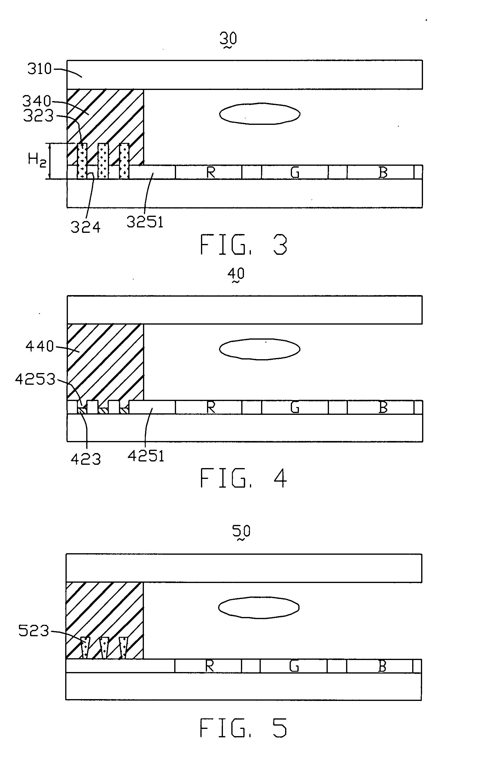
[0009] Because the whole area as between the patterned structure and the black matrix attaching to the sealant of the present invention is larger than that of black matrix attaches to the sealant of the conventional art. The adhesion between the patterned structure and the sealant of the present invention is larger than that of the conventional art. After the sealant is formed on the black matrix that is formed at a peripheral region of the base, the patterned structure provides the force parallel to the second substrate to keep the sealant on the same location of the surface of the second substrate because the protrusions are embedded within the sealant. Furthermore, the adhesion between the patterned structure and the sealant can also be increased by the material of the patterned structure and the sealant.

Problems solved by technology

Further, a liquid crystal display device is thin and lightweight.
Therefore, the liquid crystal display device 10 is liable to become impaired or even destroyed.

Method used


Image

  • Liquid crystal display device with patterned black matrix for sealant
  • Liquid crystal display device with patterned black matrix for sealant
  • Liquid crystal display device with patterned black matrix for sealant

Examples


first embodiment

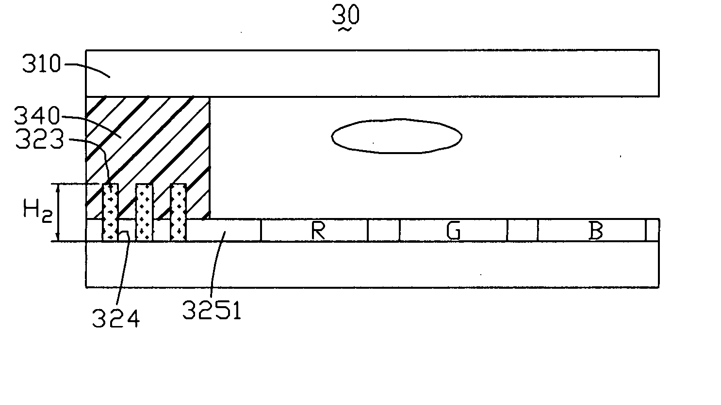
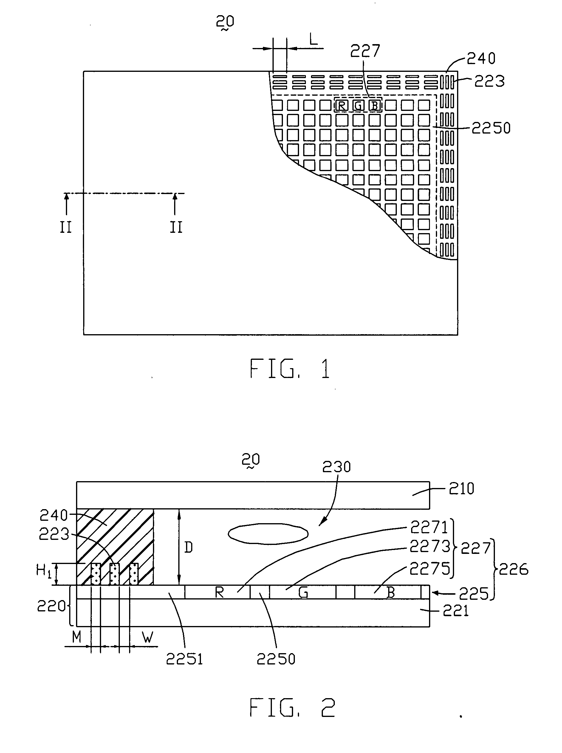
[0031] Referring to FIG. 1 and FIG. 2, a liquid crystal display device 20 of the present embodiment includes a first substrate 210, a second substrate 220 being disposed to spatially oppose to the first substrate 210, a sealant 240 and a liquid crystal layer 230. The liquid crystal layer 230 is sealed within a cavity formed by the sealant 240, the first substrate 210 and the second substrate 220. Other elements that are not important for the features of the present embodiment are not depicted within the figures.

[0032] The second substrate 220 includes a base 221, a color filter layer 226 and a patterned structure. The patterned structure has a plurality of strip-shaped protrusions 223 arranged in rows and columns on a surface of the second black matrix 2251. The patterned structure of this embodiment has many protrusions 223 for embedded with the sealant 240. The color filter layer 226 includes a color layer 227 and a black matrix 225 including a first black matrix portion 2250 and ...

fifth embodiment

[0041] Referring to FIG. 6, a liquid crystal display device 60 in the fifth embodiment includes a first substrate 610, a second substrate 620 being disposed to spatially oppose to the first substrate 610, a sealant 640 and a liquid crystal layer 630. The liquid crystal layer 630 is sealed within a cavity formed by the sealant 640, the first substrate 610 and the second substrate 620.

[0042] The second substrate 620 includes a base 621 and a color filter layer 626. The color filter layer 626 includes a color layer 627 and a black matrix 625 that includes a first black matrix portion 6250 and a second black matrix portion 6251. The color layer 627 includes red units 6271, green units 6273 and blue units 6275. The red units 6271, the green units 6273 and the blue units 6275 are disposed individually between the liquid crystal layer 630 and the base 621. The first black matrix portion 6250 is formed separately between the red units 6271, the green units 6273 and the blue units 6275 as vi...


PUM


Abstract

An exemplary liquid crystal display device includes a first substrate, a second substrate being disposed to spatially oppose to the first substrate and a sealant. The second substrate includes a base and a black matrix with a patterned structure. The sealant is formed between the first substrate and the patterned structure of the black matrix.

Description

FIELD OF THE INVENTION [0001] The present invention relates to liquid crystal display (LCD) devices, and more particularly to a sealing structure for an LCD device. GENERAL BACKGROUND [0002] Nowadays, more and more modern apparatuses, e.g. televisions, notebook computers, cell phones and personal digital assistants, include liquid crystal display devices. Liquid crystal display devices are popular because they can provide information and images with low power consumption. Further, a liquid crystal display device is thin and lightweight. Two important kinds of liquid crystal display device are the transmissive LCD device and the reflective LCD device. A transmissive LCD device typically includes at least one liquid crystal display panel together with a backlight. A reflective LCD device typically includes at least one liquid crystal display panel together with a reflecting element. [0003] Referring to FIG. 16 and FIG. 17, a liquid crystal display device 10 includes a first substrate ...

Claims


Application Information

Patent Timeline
IPC IPC(8): G02F1/1333G02F1/1339
CPCG02F1/133512G02F2202/28G02F1/1339
Inventor CHAN, CHIA-MINGCHO, HUNG-SHIENHSIAO, KUN-HSING
Owner INNOLUX CORP
Learn More