
Ophthalmologic photographing apparatus

Inactive Publication Date: 2007-12-20
KK TOPCON
View PDF5 Cites 59 Cited by
  • Summary
  • Abstract
  • Description
  • Claims
  • Application Information

AI Technical Summary

Benefits of technology

[0009] Furthermore, the present invention has further object to provide an ophthalmologic photographing apparatus that can specify a rough position by a large-angle scanning mirror and observe a minute site in detail by a small-angle scanning mirror.
[0010] Still furthermore, the present invention has further object to provide an ophthalmologic photographing apparatus that can estimate a blood flow rate by scanning a part of a minute site at a high speed.
[0022] According to the present invention, it can provide an ophthalmologic photographing apparatus that can achieve a high-magnification retinal image at any position.
[0024] Furthermore, According to the present invention, it can provide an ophthalmologic photographing apparatus that can specify a rough position by a large-angle scanning mirror and observe a minute site in detail by a small-angle scanning mirror.
[0025] Still furthermore, According to the present invention, it can provide an ophthalmologic photographing apparatus that can estimate a blood flow rate by scanning a part of a minute site at a high speed.

Problems solved by technology

Since the size of a white blood cell is about 10 μm, however, it would be difficult for current retina cameras to measure it.
It would be also very difficult to take moving images of a blood flow because the amount of light which can be allowed to be incident on an eye is restricted and the line of sight is not stable.
When the number of the scanning systems is set to three or more, the apparatus construction of the conventional scanning type adaptive optics retina camera is generally enormous in size.

Method used


Image

  • Ophthalmologic photographing apparatus
  • Ophthalmologic photographing apparatus
  • Ophthalmologic photographing apparatus

Examples


Embodiment Construction

[0036] A preferred embodiment according to the present invention will be described hereunder with reference to the accompanying drawings.

1. Outline

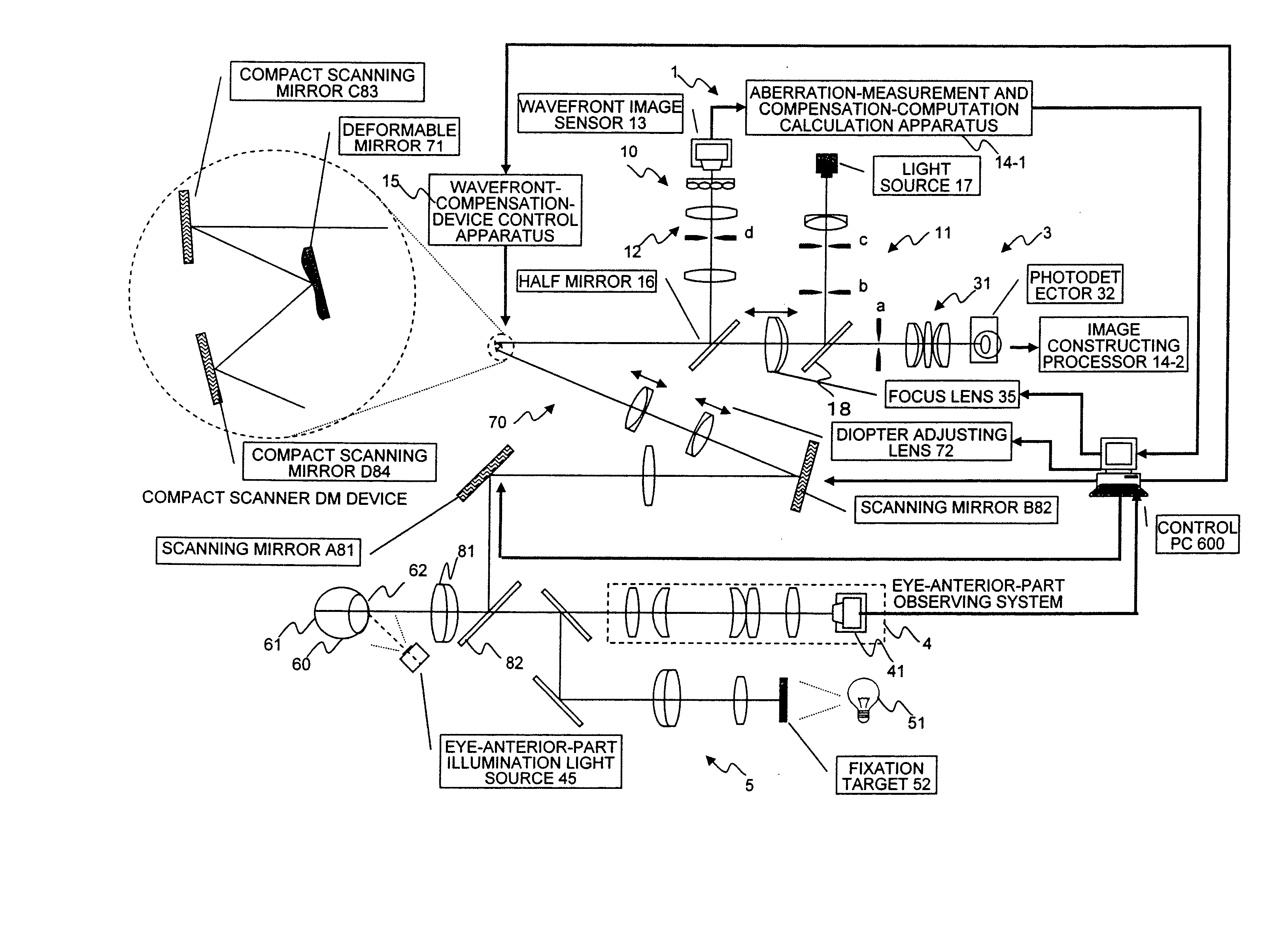
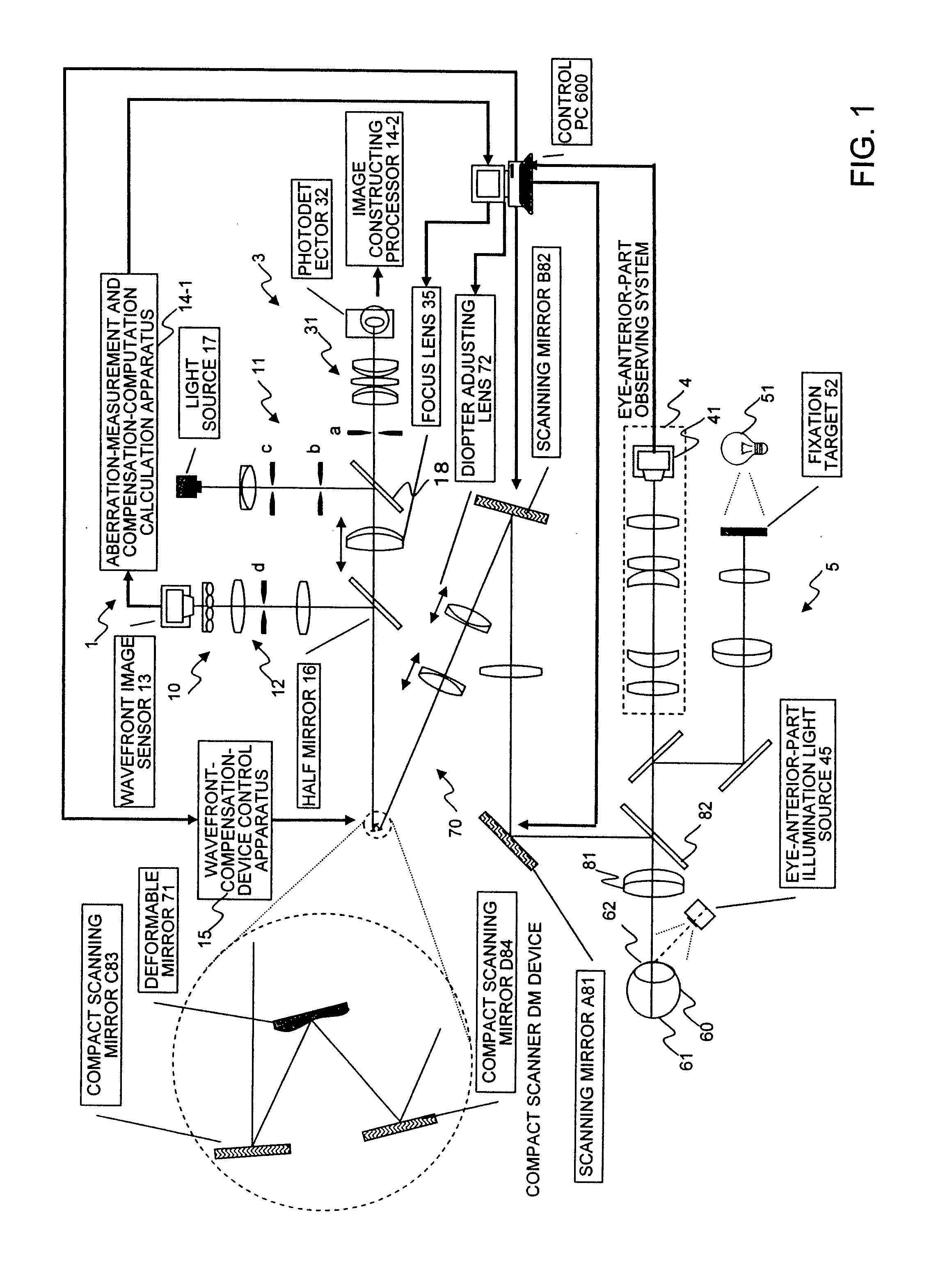
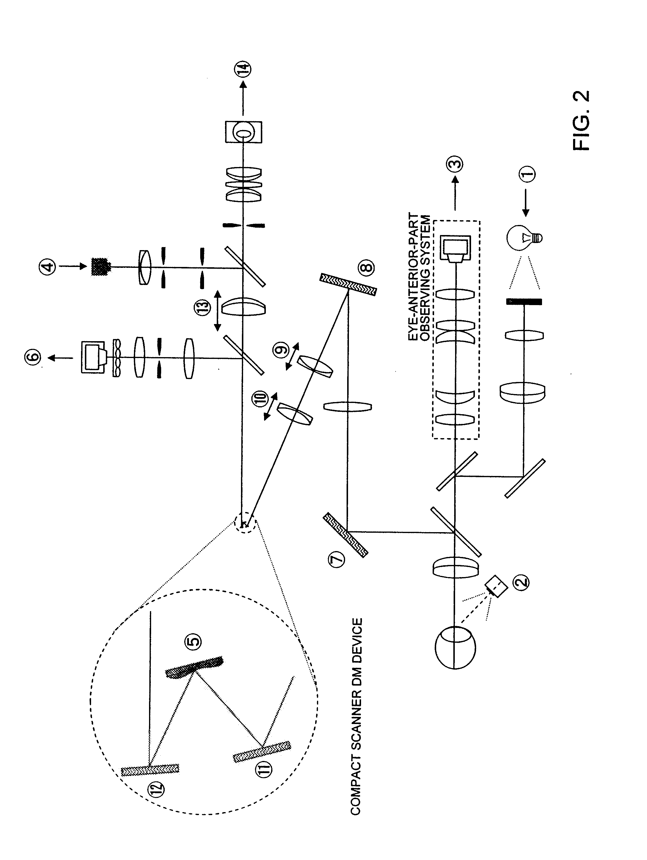
[0037] An embodiment of the present invention relates to an MEMS scanner confocal type adaptive optics retina camera that can achieve a high-magnification retinal image at any position. According to this embodiment, a retinal camera that can pick up an image with high magnification at any position can be provided by disposing two scanning mirrors adaptive to two directions of X and Y at positions near to a wavefront compensation element disposed at a pupil-conjugated position of a confocal adaptive optics retinal camera. A deformable mirror itself may be rotated in place of the scanning mirror.

[0038] Furthermore, scanning at an aimed position can be performed, the rate of blood flow can be roughly measured on the basis of a numerical variation of intensity by performing scanning one-dimensionally at a high speed.

2. Optical Arrangeme...


PUM


Abstract

Horizontal and vertical scanning mirrors for scanning over a large angle, and horizontal and vertical compact scanning mirrors for scanning over a small angle are disposed at pupil-conjugated positions. Light is emitted from a light source to a retina, and reflected light from a broad range of the retina is accumulated by a photodetector. The accumulated light is constructed as a low-magnification retinal image by an image constructing processor. A position for picking up a high-magnification image is indicated on the basis of the constructed low-magnification retinal image. The compact scanning mirrors are rotated so that a high-magnification retinal image is achieved at the indicated pickup position. The photodetector accumulates the reflection light from the retina, and constructs the high-magnification retinal image at the pickup position indicated by the image constructing processor.

Description

BACKGROUND OF THE INVENTION [0001] 1. Field of the Invention [0002] The present invention relates to an ophthalmologic photographing apparatus, and particularly to an ophthalmologic photographing apparatus having scanning mirrors of four or more systems. [0003] 2. Description of the Related Art [0004] Only eyes include blood vessels which can be directly viewed without any surgical operations in a body. If a white blood cell can be observed in a blood flow, it helps to find general disorders such as diabetes. Since the size of a white blood cell is about 10 μm, however, it would be difficult for current retina cameras to measure it. It would be also very difficult to take moving images of a blood flow because the amount of light which can be allowed to be incident on an eye is restricted and the line of sight is not stable. [0005] The following technologies have been disclosed by the assignee of present application. An eye-characteristic measurement apparatus which compensates for a...

Claims


Application Information

Patent Timeline
IPC IPC(8): A61B3/10
CPCA61B3/12A61B3/1015
Inventor YAMAGUCHI, TATSUOMIHASHI, TOSHIFUMI
Owner KK TOPCON
Features
  • Generate Ideas
  • Intellectual Property
  • Life Sciences
  • Materials
  • Tech Scout
  • Unparalleled Data Quality
  • Higher Quality Content
  • 60% Fewer Hallucinations
Learn More