Multi-Stage optical Isolator

a multi-stage, optical isolator technology, applied in the direction of generator/motor, polarizing element, instrument, etc., can solve the problems of requiring nearly double the number of optical components, bulky prior art multi-stage devices, and inability to consider practical polarization-dependent designs

Inactive Publication Date: 2007-12-20
LUMENTUM OPERATIONS LLC
View PDF6 Cites 8 Cited by
  • Summary
  • Abstract
  • Description
  • Claims
  • Application Information

AI Technical Summary

Benefits of technology

[0017]The multi-stage multi-port optical isolator is essentially a two-stage folded isolator, each stage having an isolator wherein some of the optical elements are shared between the two stages, and wherein the elements are configures to ensure that light to be isolated is directed to output ports along a same line as the input ports.

Problems solved by technology

However, in certain circumstances where a transmission system causes uncontrollable changes in polarization, the polarization state of a signal may be unknown, and thus, this earlier polarization dependent designs are not considered to be practical.
Such additional isolation has been known to be provided by using a multi-stage optical isolating device, however known prior art multi-stage devices tend to be bulky and costly to manufacture, often requiring nearly double the number of optical components that a single stage device requires.
Although the optical isolator described performs its intended function of providing multiple stages of isolation, the structure of the device does not lend itself to a practical way of inexpensive manufacture or assembly.
For example due to the presence of the corner cube prism, making a single, bulk, large isolating block and “dicing” it into a plurality of uniform complete optical isolators is not practicable.
Prior art U.S. patent application US2003 / 0058536 discloses a single stage optical isolator having a right angle prism at an end thereof for folding the beam propagating therethrough, however the isolator does not provide multiple stages of isolation.
This is not particularly useful for coupling to planar waveguide light wave circuits (PLCs) where the waveguides lie along a common line.

Method used


Image

  • Multi-Stage optical Isolator
  • Multi-Stage optical Isolator
  • Multi-Stage optical Isolator

Examples


Embodiment Construction

[0036]Throughout this specification the term polarization rotator is used to denote an element which physically rotates the polarization of a beam propagating therethrough; this is exemplified by a Faraday rotator which is a non-reciprocal rotator; however the term polarization rotator is used hereafter and is found in other prior art patents to denote a waveplate which relatively retards a beam of light passing therethrough with respect to another beam having the effect of being a reciprocal rotating element since the linear polarization state between two beams where only one passes through a waveplate “appears” to be relatively rotated with respect to the other.

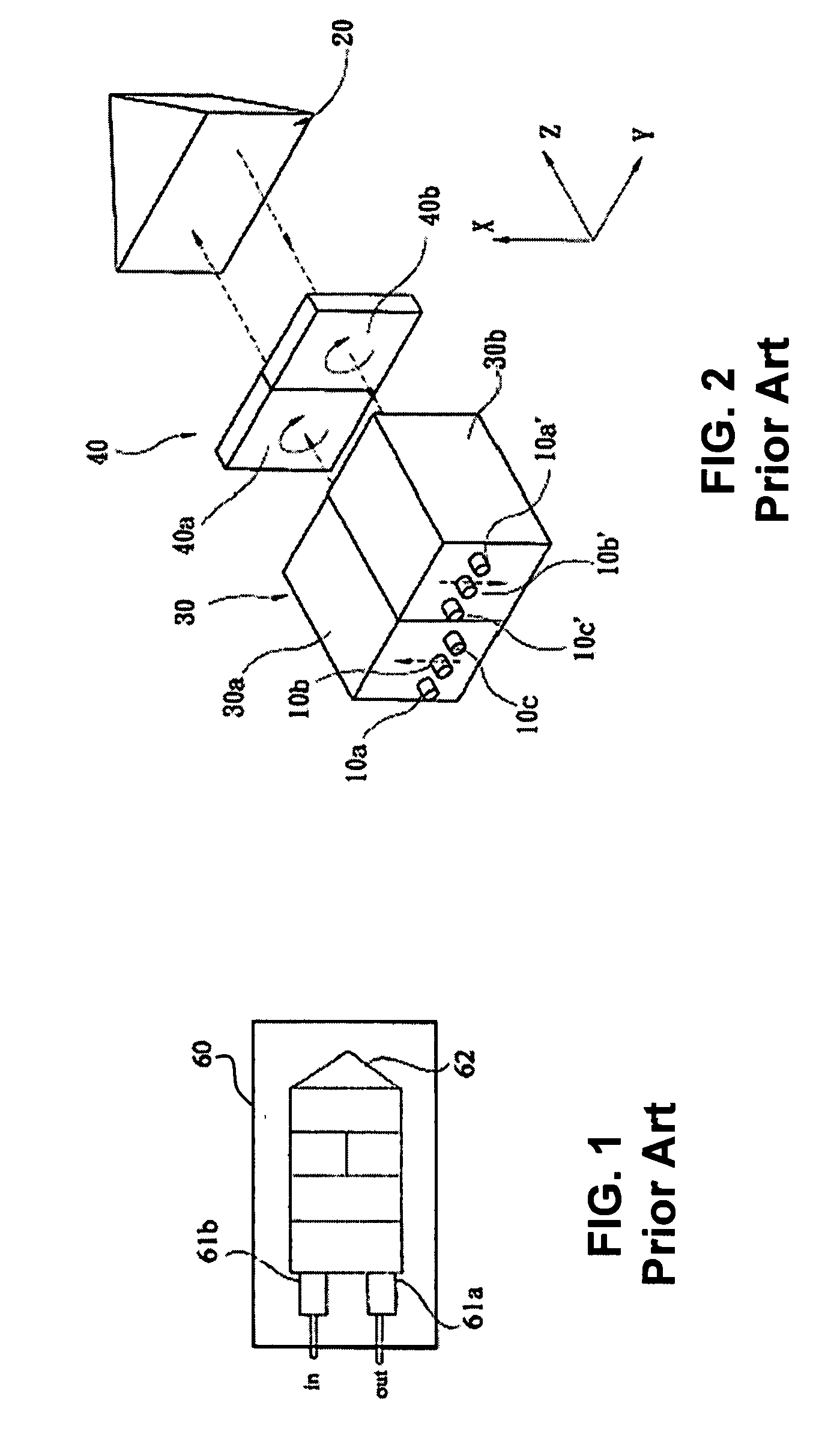
[0037]Turning now to FIG. 1, a prior art double stage isolator is shown. The isolator has a birefringent crystal 12 a Faraday (non-reciprocal) rotator 14, and a birefringent crystal 18 is disposed adjacent waveplates 16a and 16b for combining the two beams of light in the transmitting non-reflecting direction wherein two gr...


PUM


Abstract

A double stage isolator is formed of a face-to-face slabs or sheets of materials that will suitably split, combine, non-reciprocally rotate to ensure isolation in a reverse direction from output ports to respective input ports of any light launched into the input ports. A right angled Porro-prism is disposed at an end of the affixed together slabs having planar faces to direct light launched in a folded fashion to the output ports. A half waveplate is used in addition to beam splitter combiners and non-reciprocal rotators means that rotate the light by 90 degrees so as to pass a single beam in a forward propagating direction and to interchange the polarization of two sub-beams that pass through from an output port to an input port in a reverse direction.

Description

CROSS-REFERENCE TO RELATED APPLICATIONS[0001]The present invention claims priority from U.S. Patent Application No. 60 / 804,951 filed Jun. 16, 2006, which is incorporated herein by reference for all purposes.FIELD OF THE INVENTION[0002]This invention relates generally to a multi-stage optical isolator and more particularly to a reflective optical isolating device having at least two stages.BACKGROUND OF THE INVENTION[0003]Optical isolators are used in a variety of applications in optical communication systems. Generally, optical isolators are used to prevent reflective portions of transmitted signals from re-entering the transmitting device. Many older prior art designs prevent reflections from re-entering a transmitting device in a polarization-selective manner. However, in certain circumstances where a transmission system causes uncontrollable changes in polarization, the polarization state of a signal may be unknown, and thus, this earlier polarization dependent designs are not co...

Claims


Application Information

Patent Timeline
Patent Type & Authority Applications(United States)
IPC IPC(8): G02B27/28
CPCY10S372/703G02F1/093G02B6/264
Inventor COLBOURNE, PAULWILLS, GONZALO
Owner LUMENTUM OPERATIONS LLC
Why Eureka
Try Eureka