
Method and device for indicating quantizer parameters in a video coding system

a video coding system and quantization parameter technology, applied in the field of quantization parameter values in video coding systems, can solve problems such as the production of prediction error values corresponding blocks, and achieve the effect of reducing the transmission bit ra

Active Publication Date: 2007-12-20
NOKIA CORP
View PDF14 Cites 41 Cited by
  • Summary
  • Abstract
  • Description
  • Claims
  • Application Information

AI Technical Summary

Benefits of technology

This approach significantly reduces the transmission bit-rate, exemplified by a reduction from 1.2 kbps to 0.2 kbps for QP information, especially evident in constant QP scenarios, thereby improving efficiency in low-bandwidth applications like mobile video transmission.

Problems solved by technology

The method comprises encoding a frame of the digital video sequence by applying motion compensated prediction to blocks of pixels, thereby producing corresponding blocks of prediction error values.

Method used


Image

  • Method and device for indicating quantizer parameters in a video coding system
  • Method and device for indicating quantizer parameters in a video coding system
  • Method and device for indicating quantizer parameters in a video coding system

Examples


Embodiment Construction

[0098] In a preferred embodiment of the invention a video sequence specific quantization parameter (QP) is transmitted and used as a reference when coding and decoding the actual picture / slice quantization parameters. In this way there is no need to transmit a full QP for every picture / slice, but a statistically smaller difference value is transmitted and used to reconstruct the picture / slice QP, thus leading to reduction in transmission bit-rate.

[0099] Embodiments of the invention will now be described with reference to FIGS. 5 through 8.

[0100]FIG. 5 is a schematic block diagram of a video encoder 600 implemented according to the preferred embodiment of the invention. The structure of the video encoder shown in FIG. 5 is substantially identical to that of the prior art video encoder illustrated in FIG. 3, with appropriate modifications to those parts of the encoder that perform operations relating to the quantization of DCT transform coefficients and the signalling of quantizatio...


PUM


Abstract

A method and device for coding of digital video sequence, wherein an indication of quantization parameter (QP) is provided in the encoded bit-stream for decoding purposes. The QP related information is indicated by introducing a sequence level quantization parameter value SQP. More specifically, instead of coding the absolute values of picture / slice QPs, an indication of the difference ΔQP between the sequence level quantization parameter SQP and the picture / slice QP is provided. This eliminates the need to transmit a full QP for every picture / slice, and enables a statistically smaller difference value to be transmitted, thus providing a reduction in transmission bit-rate. The difference value is subsequently used in a corresponding decoder to reconstruct the picture / slice QP.

Description

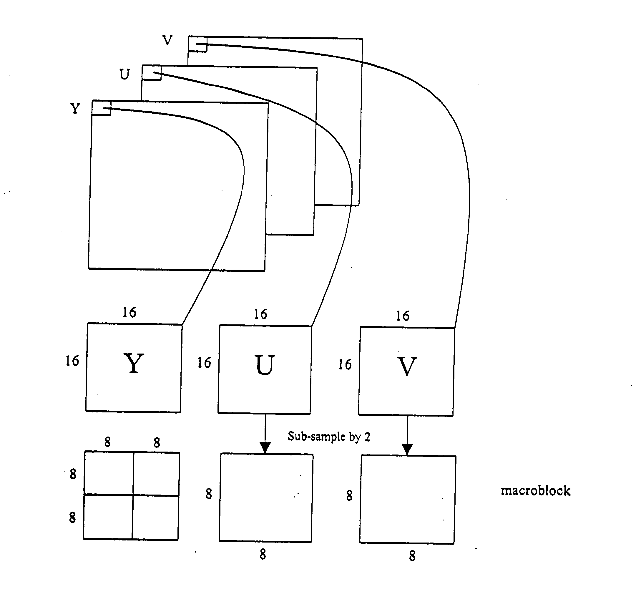
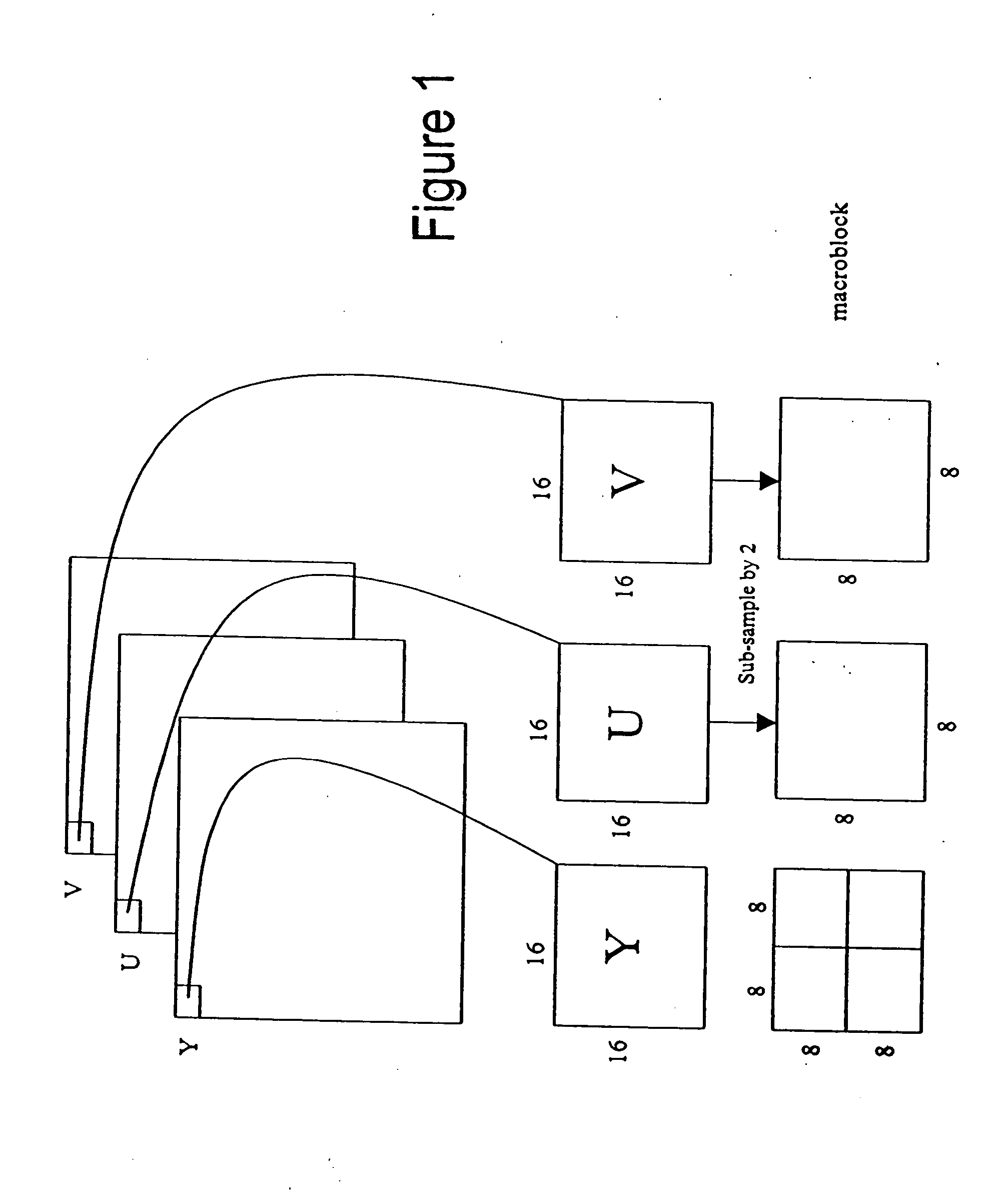
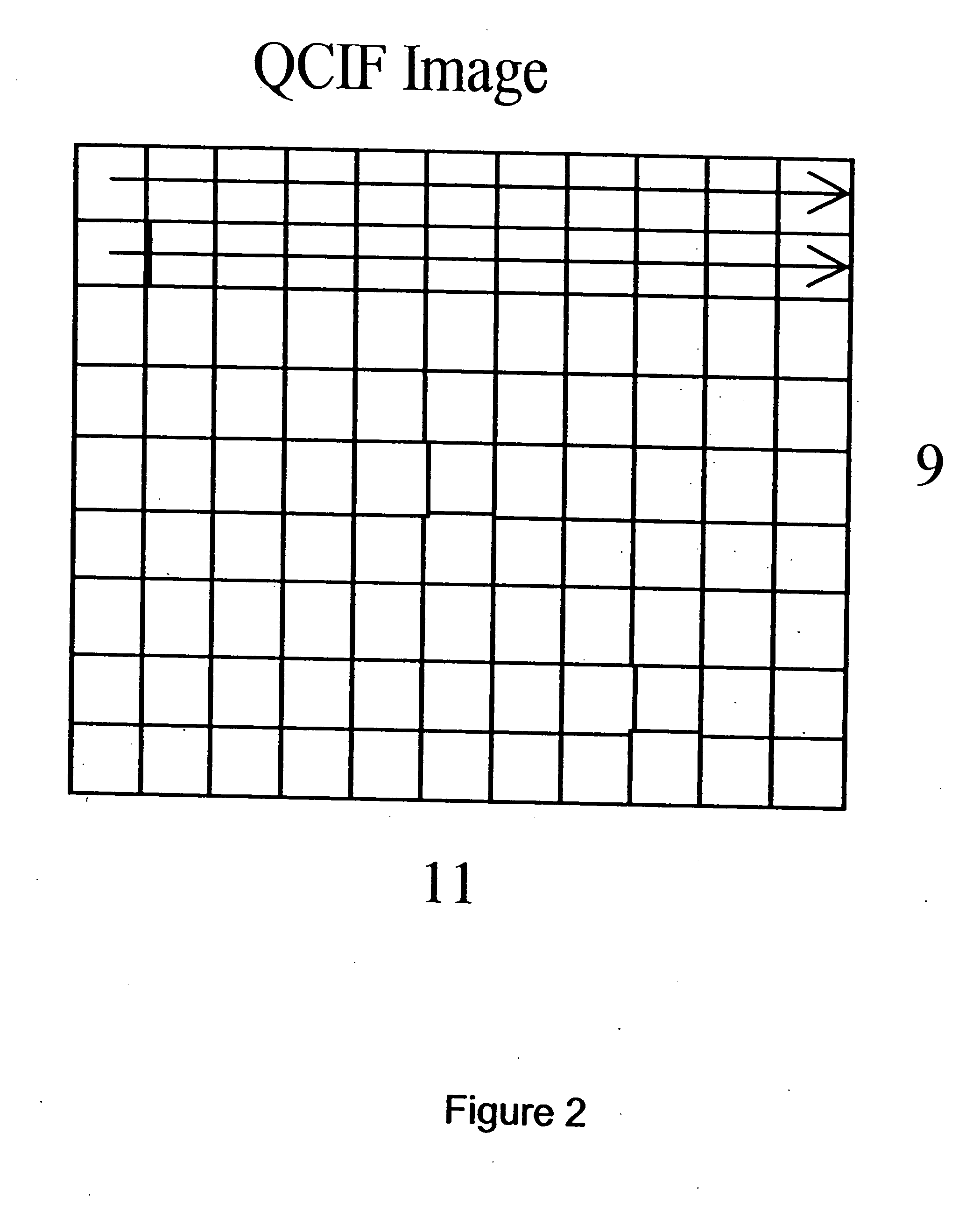
[0001] This application is a divisional application of and claims priority to a co-pending U.S. patent application Ser. No. 10 / 421,629, filed Apr. 23, 2003, which is based on and claims priority to U.S. provisional application No. 60 / 374,667, filed Apr. 23, 2002.FIELD OF THE INVENTION [0002] The invention relates to a method, an encoder, a decoder and a device for the coding of digital video. More specifically, the invention relates to the indication of quantization parameter (QP) values in a video coding system. BACKGROUND OF THE INVENTION [0003] Digital video sequences, like ordinary motion pictures recorded on film, comprise a sequence of still images, the illusion of motion being created by displaying the images one after the other, typically at a rate between 15 and 30 frames per second. [0004] Each frame of an uncompressed digital video sequence comprises an array of image pixels. In a commonly used digital video format, known as the Quarter Common Interchange Format (QCIF), a...

Claims


Application Information

Patent Timeline
Patent Type & Authority Applications(United States)
IPC IPC(8): H04N7/12H04N19/102G06T9/00H03M7/36H04N5/00H04N19/107H04N19/126H04N19/137H04N19/139H04N19/157H04N19/174H04N19/51H04N19/625
CPCH04N19/70H04N19/46H04N19/196H04N19/174H04N19/463H04N19/126H04N19/136H04N19/61H04N19/124
Inventor LAINEMA, JANI
Owner NOKIA CORP
Learn More